Object detector for a vehicle

a vehicle and object detector technology, applied in the field of object detectors, can solve the problems of difficult to sufficiently eye injury, and hypersensitivity to electromagnetic waves, so as to prevent incorrect detection of objects, reduce the burden on the control part, and improve the s/n ratio

Inactive Publication Date: 2008-09-18
OMRON AUTOMOTIVE ELECTRONICS CO LTD
View PDF9 Cites 3 Cited by
  • Summary
  • Abstract
  • Description
  • Claims
  • Application Information

AI Technical Summary

Benefits of technology

[0016]The object detector of this invention may further comprise inputting means for specifying areas for measurements. In the case of a moving target object of detection, for example, areas of interest can be freely selected according to the motion of the target object such that area data according to the invention can be generated only in areas considered to be necessary and hence the burden on the control part can be reduced.
[0017]Thus, this invention makes it possible to improve the S / N ratio and prevent incorrect detection of objects without requiring means with a complicated structure for cumulatively adding up received signals and the time series filtering.

Problems solved by technology

These requirements can be satisfied if the output power of the electromagnetic waves is increased, but the following problems are being pointed out regarding the increase in output power.
In the case of ordinary electromagnetic waves, there is the possibility of hypersensitivity to electromagnetic waves or ill effects to the brains if a human body is directly exposed to high-power waves with directionality.
In the case of light such as laser light, an eye injury may be caused if irradiated by high-power laser light.
By merely adding up the received signals, however, it is difficult to sufficiently improve the S / N ratio because, when the object has moved, the received signals before the move remain in the integrated or added value.
The method of using a time series filter also has problems because the received signals are not attenuated immediately but remains as an image because of the presence of the filter time constant although the object has actually left the area of measurement.
In other words, the devices according to these documents could not prevent erroneous detection of objects while maintaining the S / N ration on a sufficiently high level.

Method used


Image

  • Object detector for a vehicle
  • Object detector for a vehicle
  • Object detector for a vehicle

Examples


Embodiment Construction

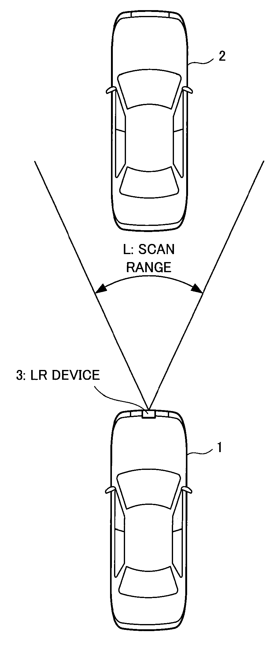
[0032]FIG. 1 shows a vehicle to which an object detector embodying this invention is mounted. Explained more in detail, it shows one's own vehicle 1 detecting a front going vehicle 2 by means of its object detector.

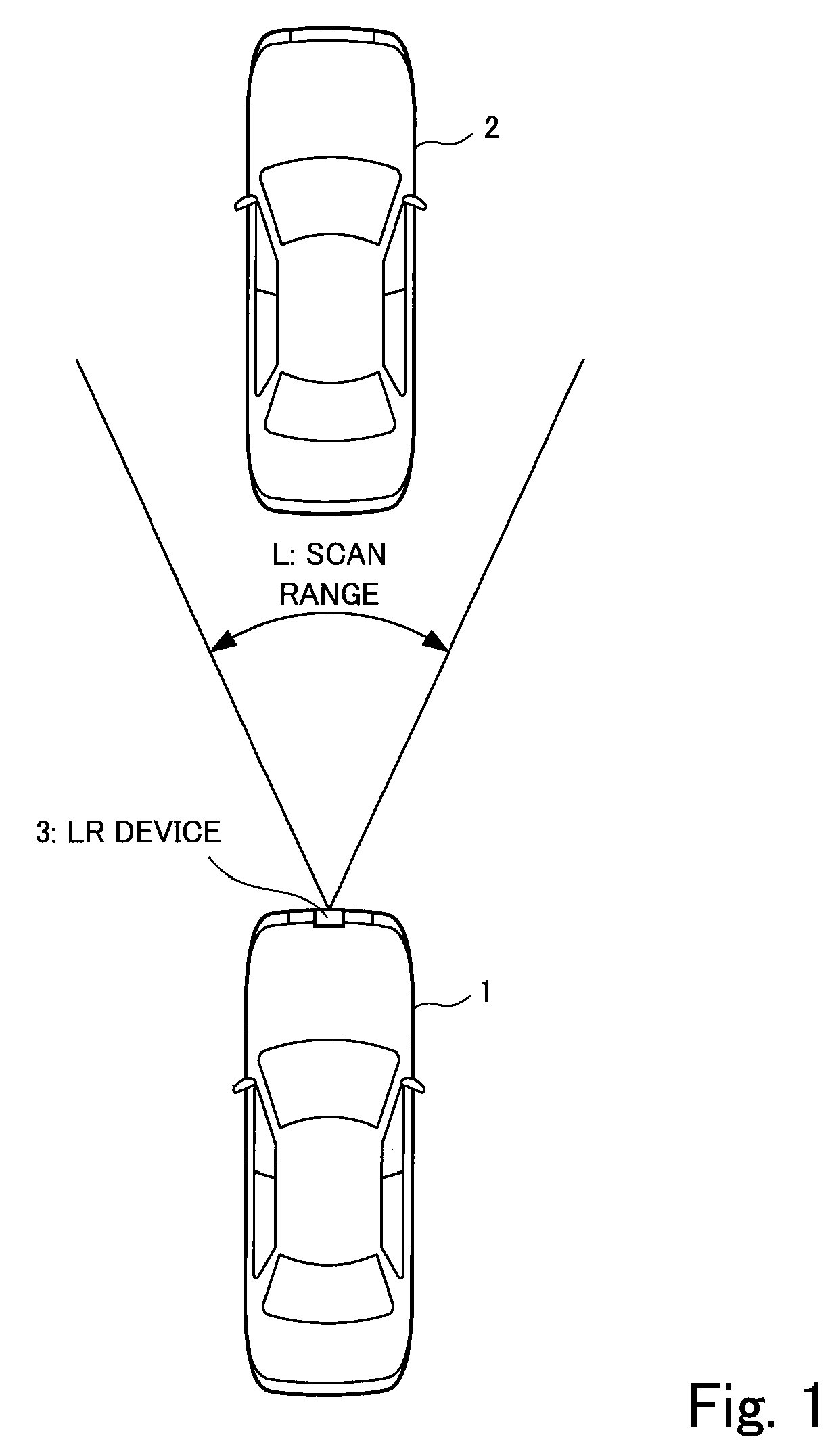
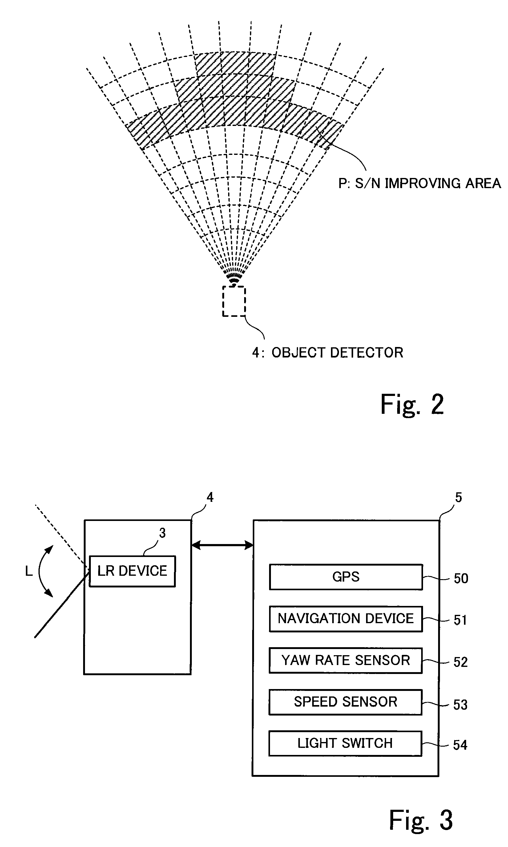
[0033]The object detector is provided with a laser radar device (hereinafter referred to as the LR device) 3 adapted to emit laser light which is a kind of electromagnetic wave beam. This LR device 3 is attached to the front part of the own vehicle 1 and serves to emit laser light forward and to scan a target area (or a scan area) L repeatedly and to receive at each scan reflected light from an object (such as the front going vehicle 2 in the example of FIG. 1) that may be present in front. Although the object detector will detect not only the front going vehicle 2 but also every objects that may be present in front, the front going vehicle 2 will be often mentioned as the example of object in front for convenience of description but it may sometimes be also referred to a...


PUM


Abstract

An object detector for a vehicle transmits a beam of electromagnetic waves forward to scan a target area, receives reflected waves from an object in front, and detects the object from received signals. Received signals are cumulatively added up for each of areas into which the target area is divided. Noise is removed from obtained data by time series filtering. If the value of a peak in data is less than that of the corresponding peak obtained in the previous scan by more than a specified value, such data are considered as an after image and not detected as an object.

Description

[0001]This application claims priority on Japanese Patent Application 2007-067356 filed Mar. 15, 2007.BACKGROUND OF THE INVENTION[0002]This invention relates to an object detector for mounting to a mobile structure such as a vehicle for detecting an object such as an obstacle that may be present in front.[0003]An adaptive cruise control (ACC) device mounted to an automobile is connected to an object detector adapted to detect an object such as a front going vehicle or a person that may be present in front by scanning a frontal area with a beam of electromagnetic waves such as light and measuring the length of time from the time of transmitting the electromagnetic waves and the time of receiving reflected waves.[0004]Such an object detector is required to have an appropriate range of measurable distances and an improved detection ratio for an object with low reflectivity by improving its S / N ratio, as well as an improved detection ratio for moving objects. These requirements can be s...

Claims


Application Information

Patent Timeline
Patent Type & Authority Applications(United States)
IPC IPC(8): G08G1/01G01S17/931
CPCG01S7/487G01S7/4873G01S17/936G01S17/42G01S17/931
Inventor MITANI, SHIGETOMO
Owner OMRON AUTOMOTIVE ELECTRONICS CO LTD
Why Eureka
Try Eureka