Battery pack assembly with integrated heater

a battery pack and heater technology, applied in the direction of heater elements, secondary cell servicing/maintenance, electrochemical generators, etc., can solve the problems of lithium ion battery use, battery pack life cycle capacity or charge/discharge capability may be greatly reduced, and battery pack performance may begin to lose its capacity or ability to change or discharge, etc., to achieve excellent battery pack performance, save implementation costs, and overall reliability

Inactive Publication Date: 2008-09-18
ENERDEL
View PDF40 Cites 50 Cited by
  • Summary
  • Abstract
  • Description
  • Claims
  • Application Information

AI Technical Summary

Benefits of technology

[0009]The assembly of the subject invention provides excellent battery pack performance by allowing heating of the battery pack by the heating device. Furthermore, the supply of electric current to the heating device is acquired directly from the battery pack itself, thereby negating the need for an auxiliary current source. Also, the connection pads and tabs allow direct connection of the flexible heating device to the battery. This direct connection permits acquisition of electric current from the heater without additional wiring, thus saving implementation costs as well as overall reliability of the assembly. Last, by implementing the thermal sensor within the heating strip, the need for an additional external sensor is negated.

Problems solved by technology

Due to the characteristics of lithium ion batteries, the battery pack operates within an ambient temperature range of −20° C. to 60° C. However, even when operating within this temperature range, the battery pack may begin to lose its capacity or ability to change or discharge should the ambient temperature fall below 0° C. Depending on the ambient temperature, the life cycle capacity or charge / discharge capability of the battery may be greatly reduced as the temperature strays below 0° C. Nonetheless, it may be unavoidable that a lithium ion battery be used where the ambient temperature falls outside an optimum temperature range of 0 to 60° C.

Method used


Image

  • Battery pack assembly with integrated heater
  • Battery pack assembly with integrated heater
  • Battery pack assembly with integrated heater

Examples


Embodiment Construction

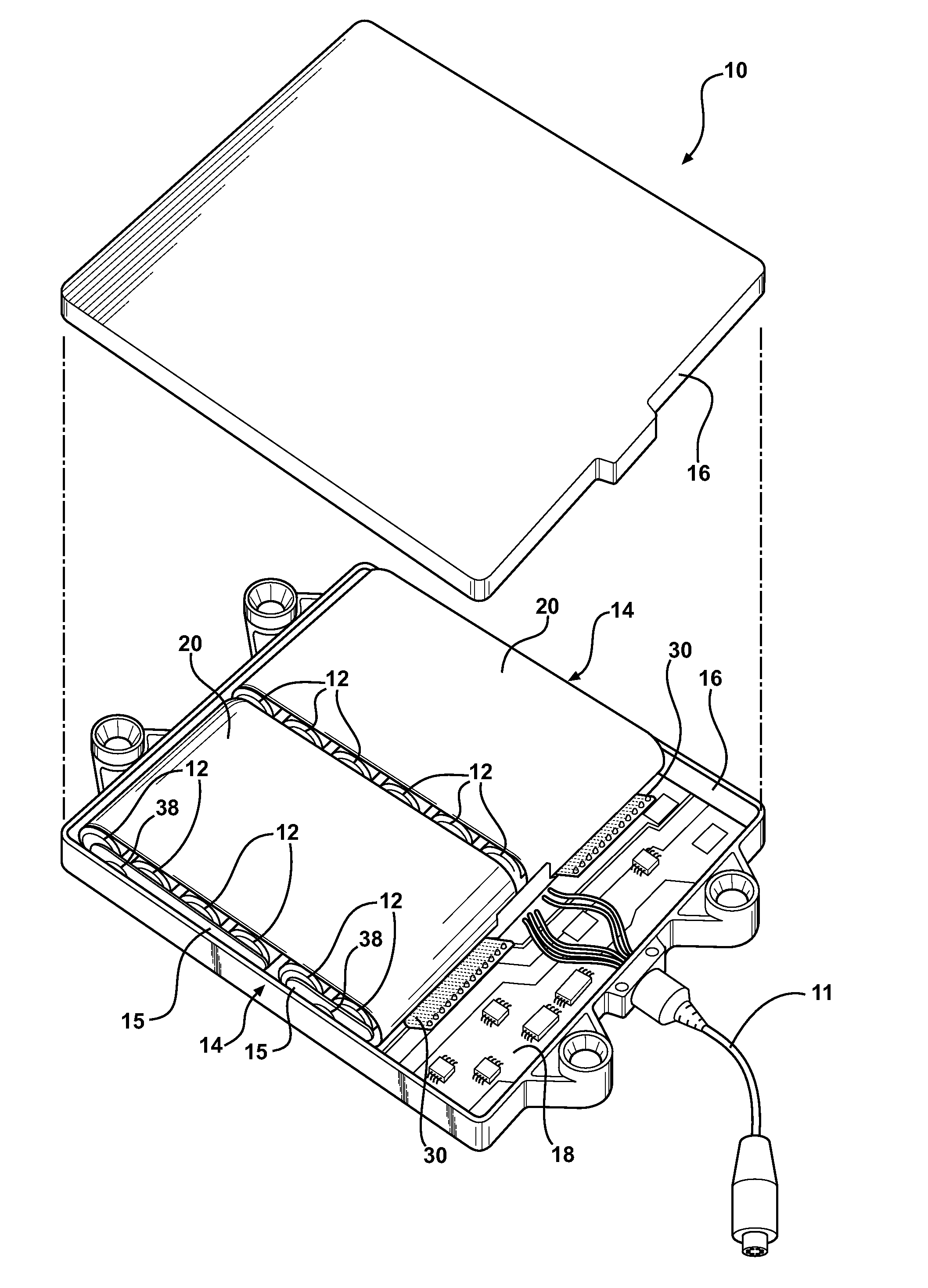
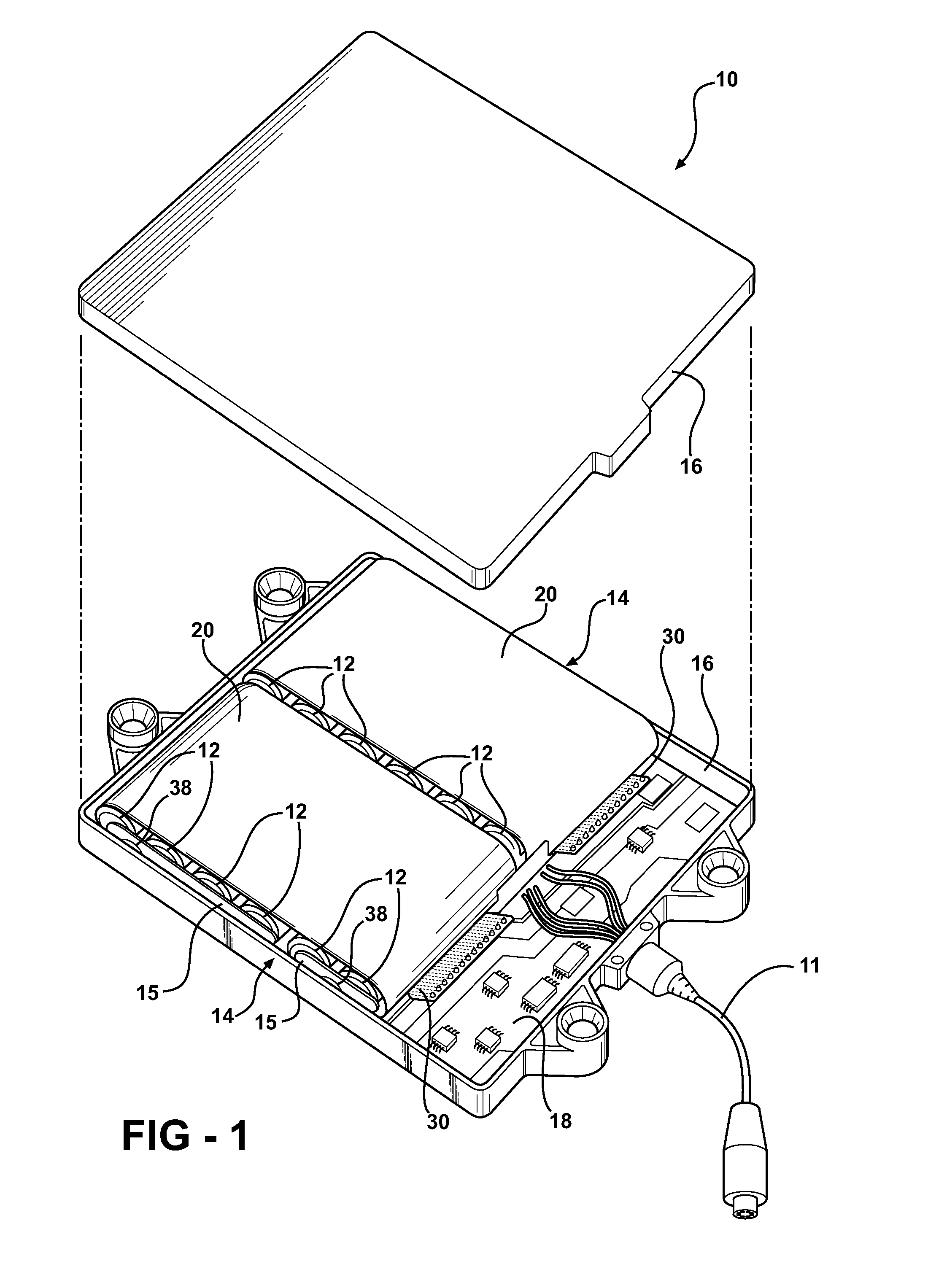
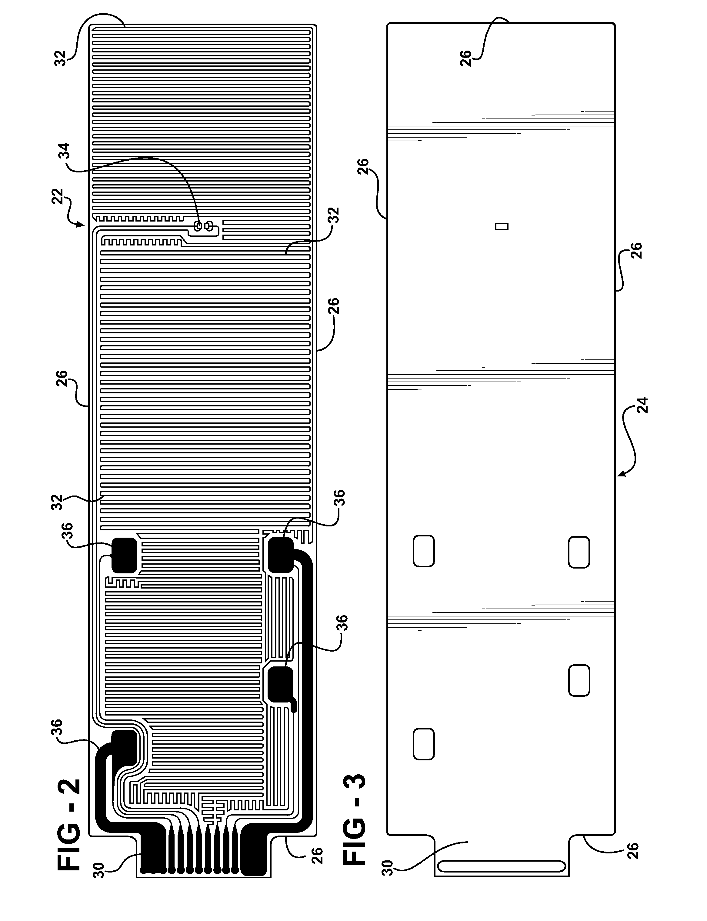
[0015]Referring to the Figures, wherein like numerals indicate corresponding parts throughout the several views, a battery pack assembly is shown at 10.

[0016]Referring to FIG. 1, the assembly 10 of the illustrated embodiment may be utilized to power an electrical load (not shown). Connection of the electrical load to the assembly 10 is via a cable 11. However, those skilled in the art realize alternative utilizations of the assembly 10.

[0017]The battery pack assembly 10 includes a plurality of cells 12 disposed adjacent one another and electrically interconnected to form a battery pack 14. In the illustrated embodiments, each cell 12 is a cylindrically shaped, lithium ion cell 12 having an anode (not labeled) and a cathode (not labeled) as is well known to those skilled in the art. The battery pack 14 includes six cells 12 are arranged in three pairs. Each pair of cells 12 are electrically connected in parallel and the three pairs of cells 12 are connected in series. Furthermore, ju...


PUM

PropertyMeasurementUnit
temperatureaaaaaaaaaa

Abstract

A battery pack assembly for providing electric power to a load includes a battery pack, preferably made up of a plurality of lithium ion cells. A heating device formed of a flexible material flexes and covers at least part of the battery pack. The heating device includes a meandering heating strip. A thermal sensor is surrounded by the heating strip to sense the temperature of the battery pack. Electric current is applied to the heating strip to heat the battery pack when its temperature falls too low, thus improving performance of the battery pack. The heating device also includes a plurality of tabs extending beyond the peripheral sides of the heating device for direct connection to the cells. Thus, electric current for the heating strip is provided directly from the cells of the battery pack.

Description

CROSS REFERENCE TO RELATED APPLICATION[0001]This application claims the benefit of U.S. provisional application No. 60 / 906,933 filed Mar. 14, 2007, which is incorporated by reference.BACKGROUND OF THE INVENTION[0002]1. Field of the Invention[0003]The subject invention relates generally to a battery pack assembly with an integrated heater.[0004]2. Description of the Prior Art[0005]Battery packs that contain lithium ion batteries are increasingly popular with automotive applications and various commercial electronic devices because they are rechargeable and have no memory effect. Storing and operating a lithium ion battery at an optimal operating temperature is very important to allow the battery to maintain a charge for an extended period of time. Due to the characteristics of lithium ion batteries, the battery pack operates within an ambient temperature range of −20° C. to 60° C. However, even when operating within this temperature range, the battery pack may begin to lose its capac...

Claims


Application Information

Patent Timeline
Patent Type & Authority Applications(United States)
IPC IPC(8): H01M10/50H01M10/48
CPCH01M10/0525H01M10/4207H01M10/425H01M10/5081H01M10/5006H01M10/503H01M10/5083H01M10/486H01M10/615H01M10/657H01M10/6571H01M10/643Y02E60/10
Inventor FATTIG, ROBERT N.
Owner ENERDEL
Why Eureka
Try Eureka