
Fabric artwork with mounting assembly for nesting in frame

Inactive Publication Date: 2008-09-25
SLAUTTERBACK FREDERICK A
View PDF14 Cites 21 Cited by
  • Summary
  • Abstract
  • Description
  • Claims
  • Application Information

AI Technical Summary

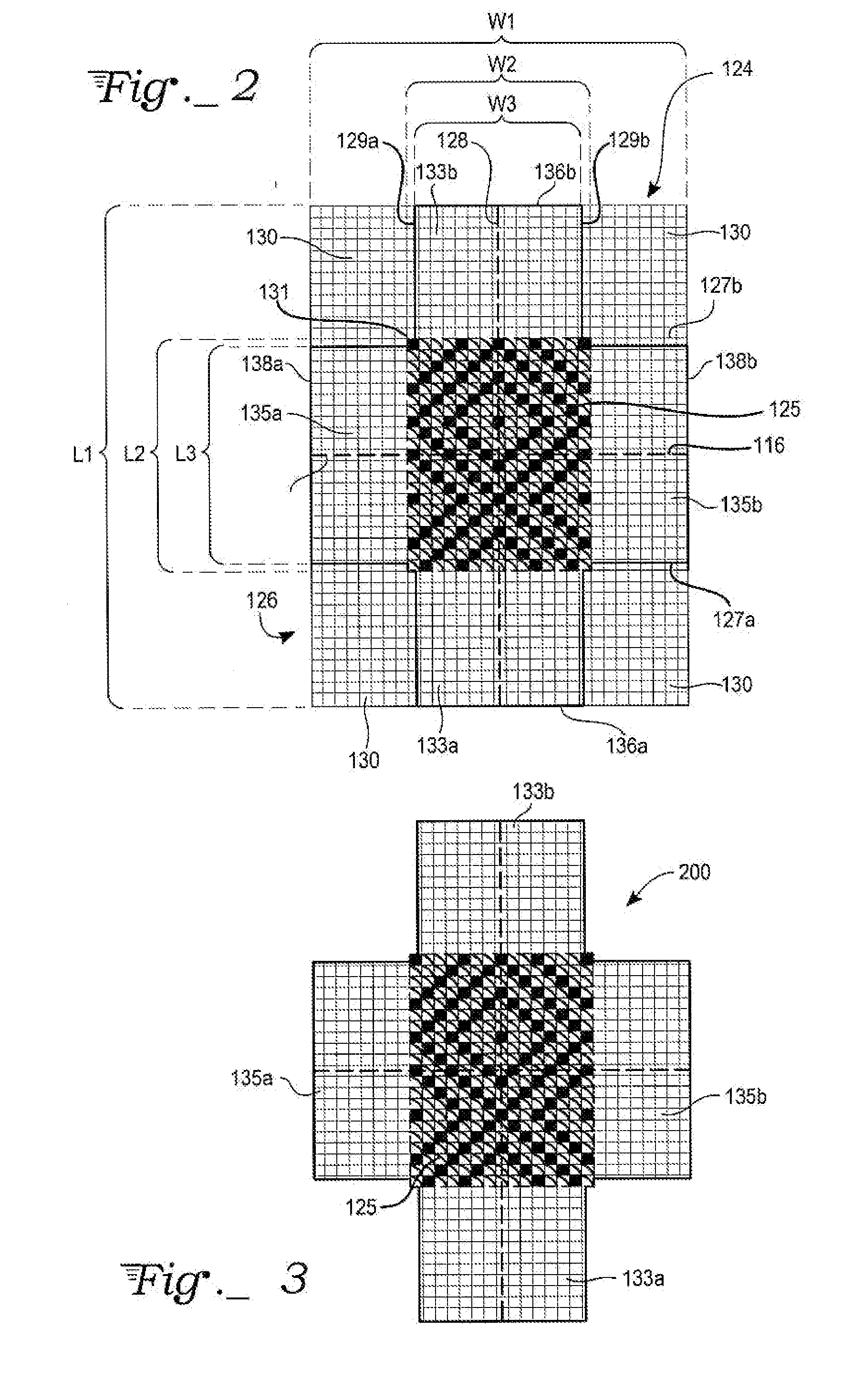
Benefits of technology

[0010]A composite backing structure preferably employs a first double sided adhesive film, a substrate attached to the first adhesive film and a second double sided adhesive film attached to the substrate in a sandwich construction with exposed adhesive facing outwardly on both sides. Alternatively, a composite backing structure can be a layer of semi-viscous adhesive spread uniformly. To avoid contact of semi-viscous adhesive with the fabric artwork composite backing structures involving adhesive films are preferred for the upper two composite backing structures. Double sided adhesive film is commercially available.
[0011]A first composite backing structure is applied against the center section of the fabric art. A first set of tabs is folded beneath the first composite backing structure and attached to exposed adhesive film. Preferably the tabs are cut so that they do not overlap but rather fit like double doors closing over exposed adhesive film of the composite backing structure such that folded tabs form a substantially flat surfa

Problems solved by technology

However, although the perimeter boundary is hidden from view, folding the canvas at each of the canvas corners tends to be problematic.
Consequently, the unstitched canvas at these right-angle corners may be difficult to hide, arid hence may be unsightly.
However, when mounted, a rabbet also tends to cover a portion of the stitchwork, further detracting from the full presentation of the needlework, particularly with framed needlepoint jewelry applications, where the actual size of the stitchwork tends to be relatively small.

Method used


Image

  • Fabric artwork with mounting assembly for nesting in frame
  • Fabric artwork with mounting assembly for nesting in frame
  • Fabric artwork with mounting assembly for nesting in frame

Examples


Embodiment Construction

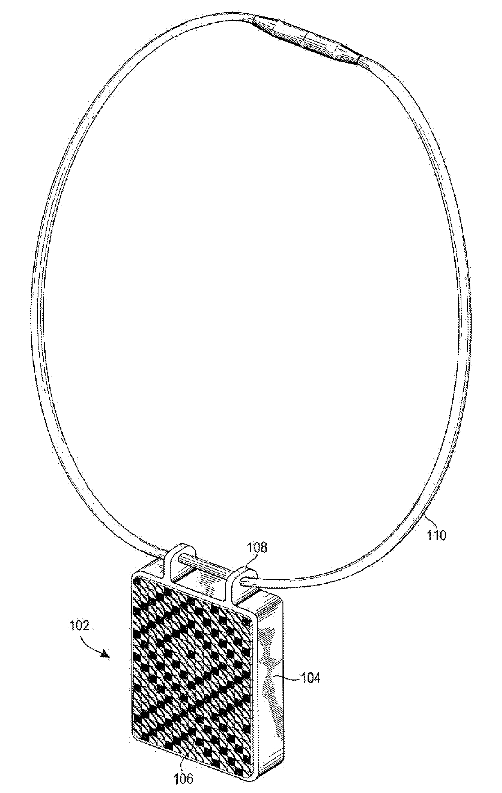
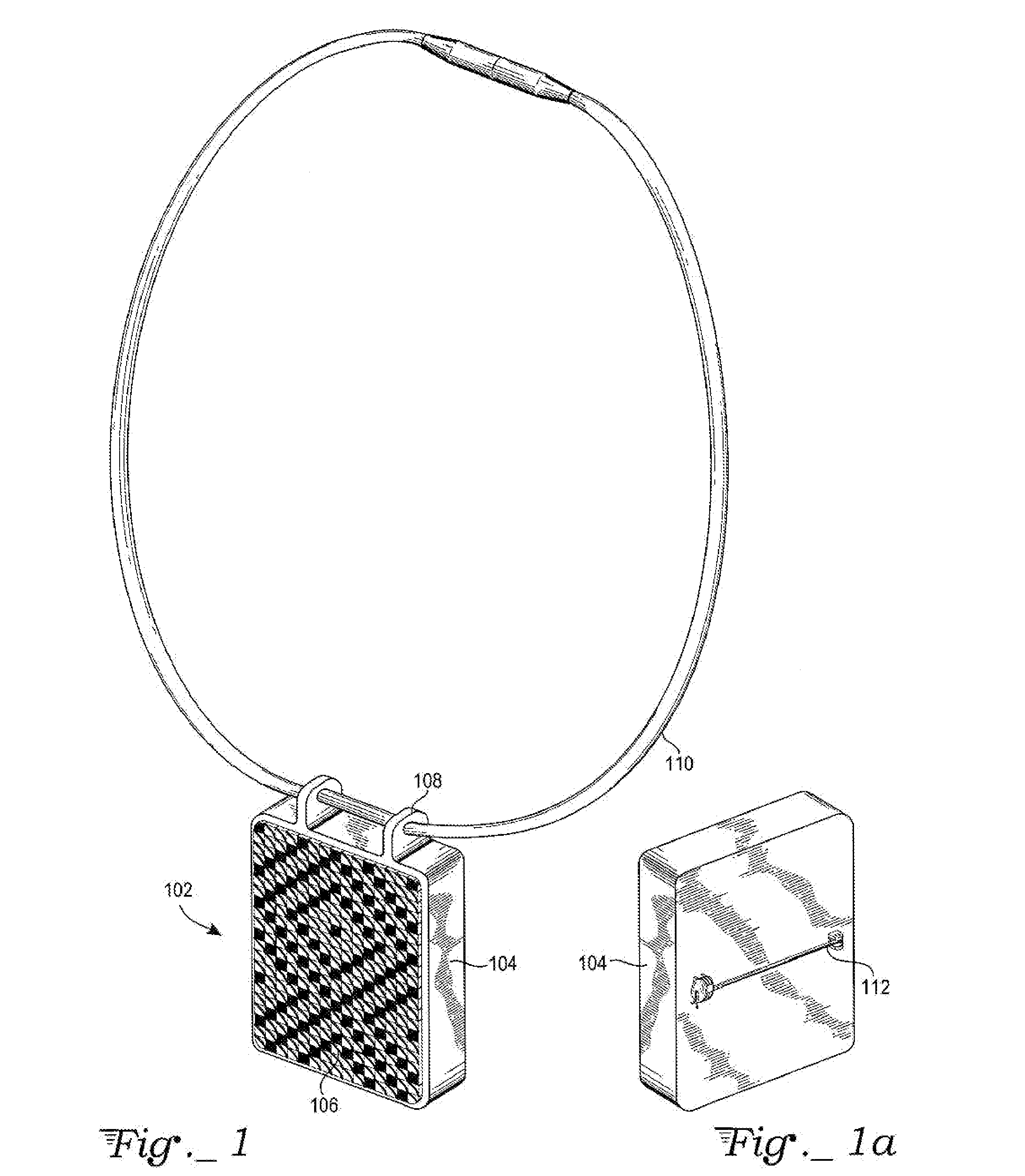
[0025]Referring to FIG. 1, a fabric artwork pendant 102 may be coupled to an attachment structure 110, such as a necklace, with a set of eyelets 108 formed on a special frame 104 of the present invention. In general, frame 104 may be manufactured from any suitably machinable, tooled, or molded material, such as metals e.g. aluminum, copper, steel, etc. or plastic, wood, ceramic, etc., preferably as a unitary article with a central well for the needlepoint artwork and optional integral eyelets 108. In this example, a pendant frame is shown with peripheral bosses, in this case eyelets, adaptable for jewelry uses. As an alternative to peripheral bosses, the backside of the frame could be provided with a pin to form a brooch. However other frames may be used, such as hanging frames, etc. The frame has a central well. typically one-eighth to three-eighths inches deep to accommodate a fabric artwork. The depth of the well is adjusted to the thickness of the artwork so that a slight amount...


PUM


Abstract

Framed fabric artwork features an artwork canvas with an artwork body having a first set of tabs and an orthogonal second set of tabs wherein the rectangular artwork body has a back surface configured to be attached to a first composite backing structure. The first set of tabs is folded beneath the first composite backing structure and adhered to it. A second composite backing structure is configured to be attached to a lower side of the first set of tabs and the second set of tabs is folded beneath the second composite backing structure and adhered to it. A third composite backing structure is adhered to the lower side of the second set of tabs and also joined to the artwork body which, in turn, is nested in a unitary frame with a rectangular well with upright walls at an outer periphery. The outer periphery of the frame may have bosses adaptable for jewelry uses.

Description

TECHNICAL FIELD[0001]The present invention generally relates to backing assemblies incorporating fabric works of art for mounting in special frames.BACKGROUND OF THE INVENTION[0002]Needlepoint exemplifies fabric works of art. It uses thread stitches in woven canvas in order to create a new fabric. Typically employing an open grid construction, the woven canvas includes horizontal (woof) and vertical (warp) threads that are woven together to create openings, called cells, in a special needlepoint fabric. The size of the canvas is generally described by the number of cells (counts, stitches, etc.) per inch (e.g., 13 cells per inch, etc.).[0003]Needlepoint thread or filling yarn is typically pulled through the cells from the front to the back by techniques of interlacing the yarn through the woven canvas typically using a tapestry needle. The portion of the canvas with the needlepoint thread or yarn is commonly called the stitchwork, and is generally surrounded by an unstitched canvas ...

Claims


Application Information

Patent Timeline
IPC IPC(8): A47G1/06
CPCA44C1/00A44C27/00A44C25/001
Inventor SLAUTTERBACK, FREDERICK A.
Owner SLAUTTERBACK FREDERICK A
Learn More