Suspension equipped with vibration sensor and manufacturing method thereof

a technology of vibration sensor and suspension, which is applied in the direction of maintaining head carrier alignment, integrated arm assembly, instruments, etc., can solve the problems of inability to correct the correct head position shift, the vibration sensor used in the suspension is very sensitive, and the adverse effect of head positioning precision

Inactive Publication Date: 2008-09-25
TOSHIBA STORAGE DEVICE CORP
View PDF2 Cites 38 Cited by
  • Summary
  • Abstract
  • Description
  • Claims
  • Application Information

AI Technical Summary

Problems solved by technology

The suspension fixing the head slider floating over a recording medium also vibrates together with the recording medium, affecting head positioning precision adversely.
However, a vibration sensor used in a suspen

Method used


Image

  • Suspension equipped with vibration sensor and manufacturing method thereof
  • Suspension equipped with vibration sensor and manufacturing method thereof
  • Suspension equipped with vibration sensor and manufacturing method thereof

Examples


Embodiment Construction

[0025]Embodiments of the present invention will be described below with reference to attached drawings.

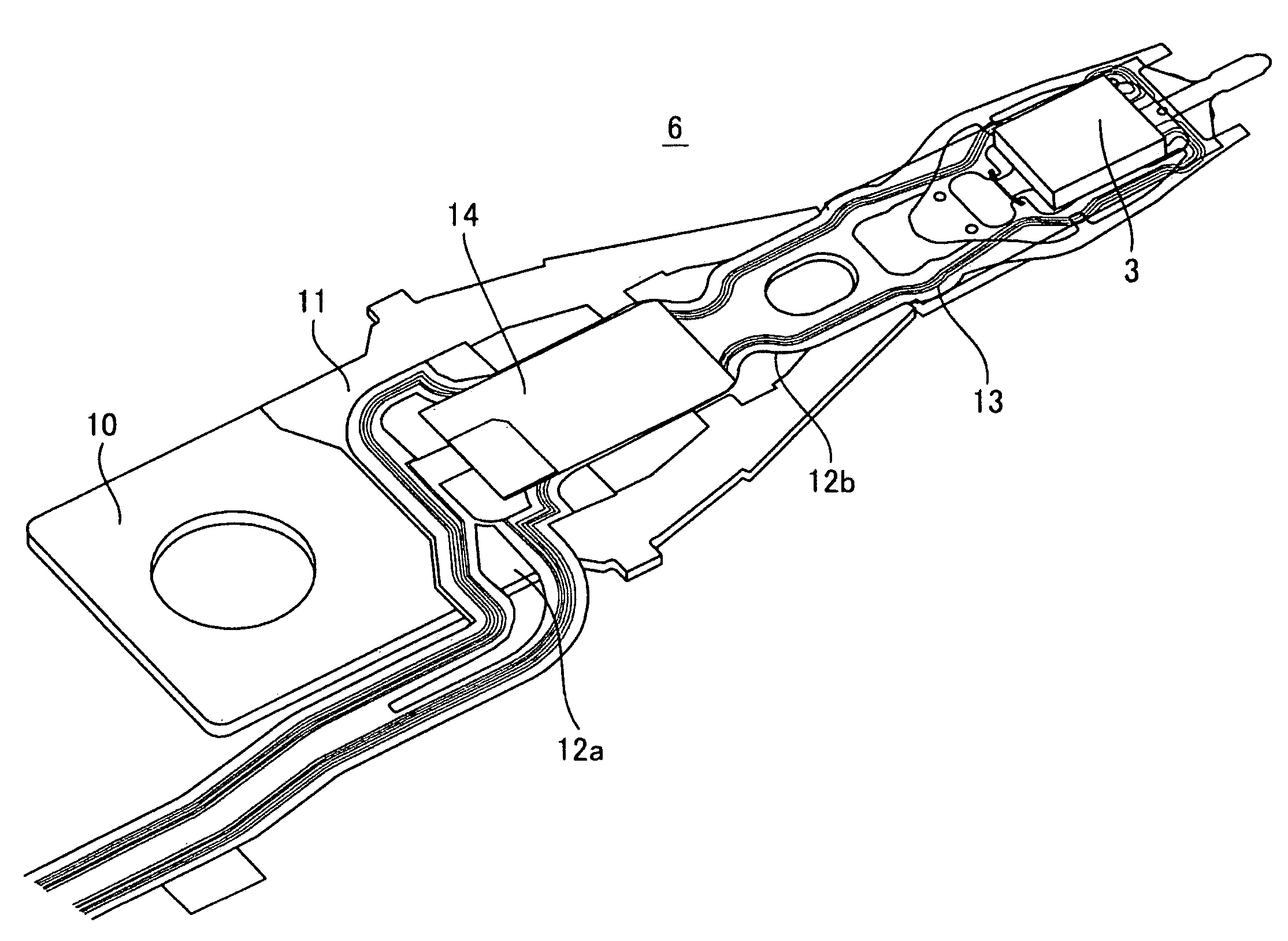
[0026]FIG. 3 shows a perspective view of a suspension of the present invention. In the suspension 6, a load beam 11 is fixed to a base plate 10 to be connected to a carriage. On the load beam 11, flexures 12a and 12b and a wiring pattern 13 are arranged in order. The head slider 3 is arranged on a portion of the flexure 12b. A vibration sensor 14 is arranged on a portion of the wiring pattern 13.

[0027]FIG. 4 shows an exploded view of the suspension of the present invention. A hollow part 22 is provided in the load beam 11 to constitute a elastic part. The flexures 12a and 12b are separated by the hollow part 22 of the load beam 11. The wiring pattern 13 is formed of insulating layers 15a and 15b, a conductive wiring pattern 16, and an insulating cover layer 21. A head terminal of the head slider 3 is electrically connected to head terminal land parts 17a and 17b formed at tip parts...


PUM

PropertyMeasurementUnit
Electrical conductoraaaaaaaaaa
Piezoelectricityaaaaaaaaaa
aaaaaaaaaa

Abstract

A suspension for a hard disk drive has a vibration sensor which is impervious to influence by external noise, to obtain more stable positioning precision of the head on the suspension. The suspension has a load beam, a vibration sensor sandwiched by a first electrode and a second electrode, and a conductive wiring pattern on the load beam for electrically connecting the first electrode and the second electrode to an external detection circuit. The first electrode is sandwiched by the second electrode via the vibration sensor and a shield layer via an insulating layer. The second electrode and the shield layer are at a same potential.

Description

[0001]The present invention relates to a suspension equipped with a vibration sensor. In particular, the present invention relates to a structure of a vibration sensor with which a suspension is equipped and a manufacturing method thereof.BACKGROUND OF THE INVENTION[0002]FIG. 1 shows a perspective view of a conventional magnetic disk apparatus, and FIG. 2 shows an enlarged perspective view of an actuator shown in FIG. 1. A magnetic recording medium 2 fixed to a spindle motor 1 rotates at high speed. With this rotation, air is drawn between a head slider 3 and the magnetic recording medium 2. The head slider 3 is floated by pressurization of the air.[0003]As shown in FIG. 2, an actuator 4 has a suspension 6 at one end of a carriage 5 and a voice coil 7 at the other end. The actuator 4 is fixed rotatably to a housing 9 (FIG. 1) by a pivot through a shaft bearing 8 and moves in an approximate radius direction of the magnetic recording medium 2. Therefore, the head slider 3 mounted to t...

Claims


Application Information

Patent Timeline
IPC IPC(8): G01B7/16H01L41/22G11B5/60G11B21/21
CPCG11B5/484Y10T29/42H01L41/1132G11B5/5582H10N30/302
Inventor OHTSUKA, SHINICHIKOGANEZAWA, SHINJI
Owner TOSHIBA STORAGE DEVICE CORP
Why Eureka
Try Eureka