Vessel

a technology for liquid containers and containers, applied in the direction of containers, containers/bottles, rigid containers, etc., can solve the problems of splashing or overflow, large or sudden volume of liquid being expelled, and the ability of children to accurately control the pouring of small amounts of liquid

Inactive Publication Date: 2008-09-25
ENAHORO HENRY
View PDF9 Cites 28 Cited by
  • Summary
  • Abstract
  • Description
  • Claims
  • Application Information

AI Technical Summary

Benefits of technology

[0013]wherein at least one of the one or more spouts comprises a recess in the inner surface and an outle

Problems solved by technology

It is often difficult, especially for the elderly, to accurately control the pouring of a small amount of liquid.
The liquid may travel too quickly from the body of the bottle to the outlet resulting in a large or sudden volume of liquid being expelled due to the sharp contour between the body of the bottle and the mouth.
This may result in a splash or an overflow.
Thus, it may be difficult to avoid wastage, which, relative to the size of the dosage, may constitute a considerable proportion of the liquid.
Dripping or overflow may also cause the formation of a sticky residue on the outside surface of the mouth, which can interrupt screwing and unscrewing of the cap, or on the outside surface of the bottle, which can feel unpleasant.
In these cases, controlled pouring is required to prevent spillage outside of the receiving inlet as this would cause wastage, mess and a potential safety hazard.
Funnels are sometimes used for this application, but are no

Method used


Image

  • Vessel
  • Vessel
  • Vessel

Examples


Embodiment Construction

[0064]Referring to the drawings, various vessels are provided in accordance with embodiments of the present invention. The vessels may be used to hold and dispense fluids, such as liquid medications, liquid ingredients, engine oil, water, milk, paints or dyes.

[0065]It should be noted in the following description that like or the same reference numerals in different embodiments denote the same or similar features.

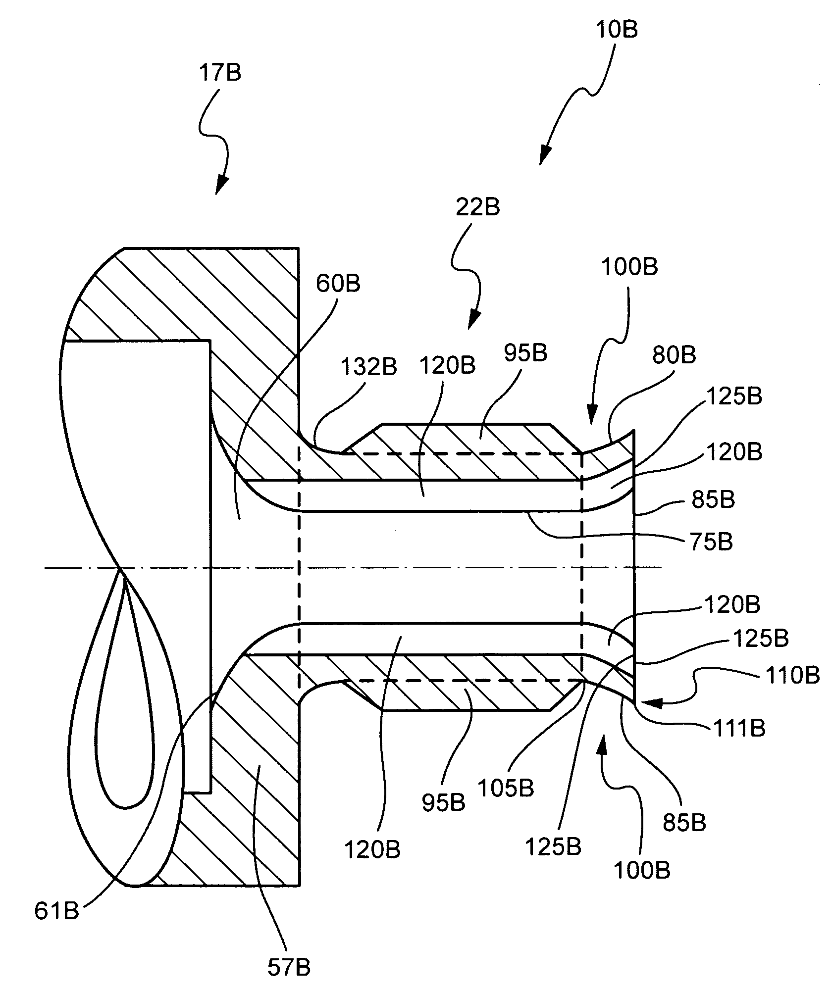
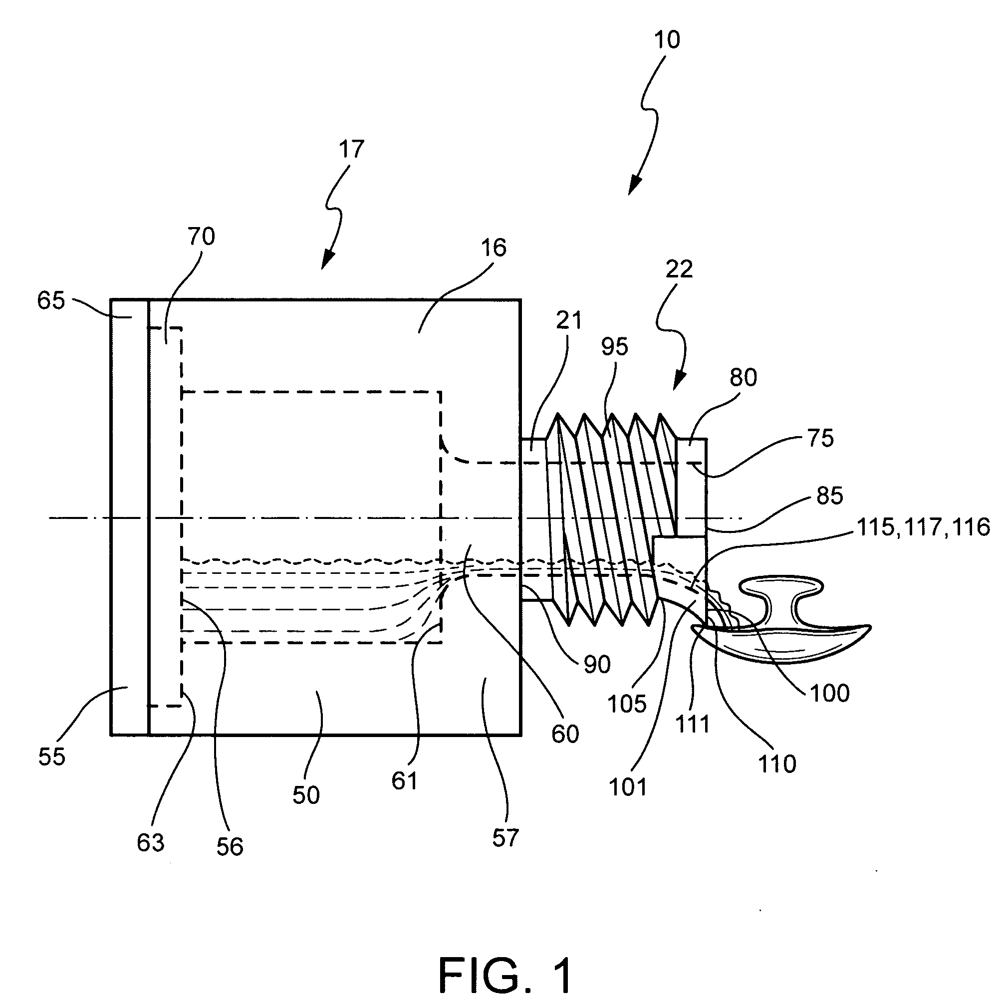
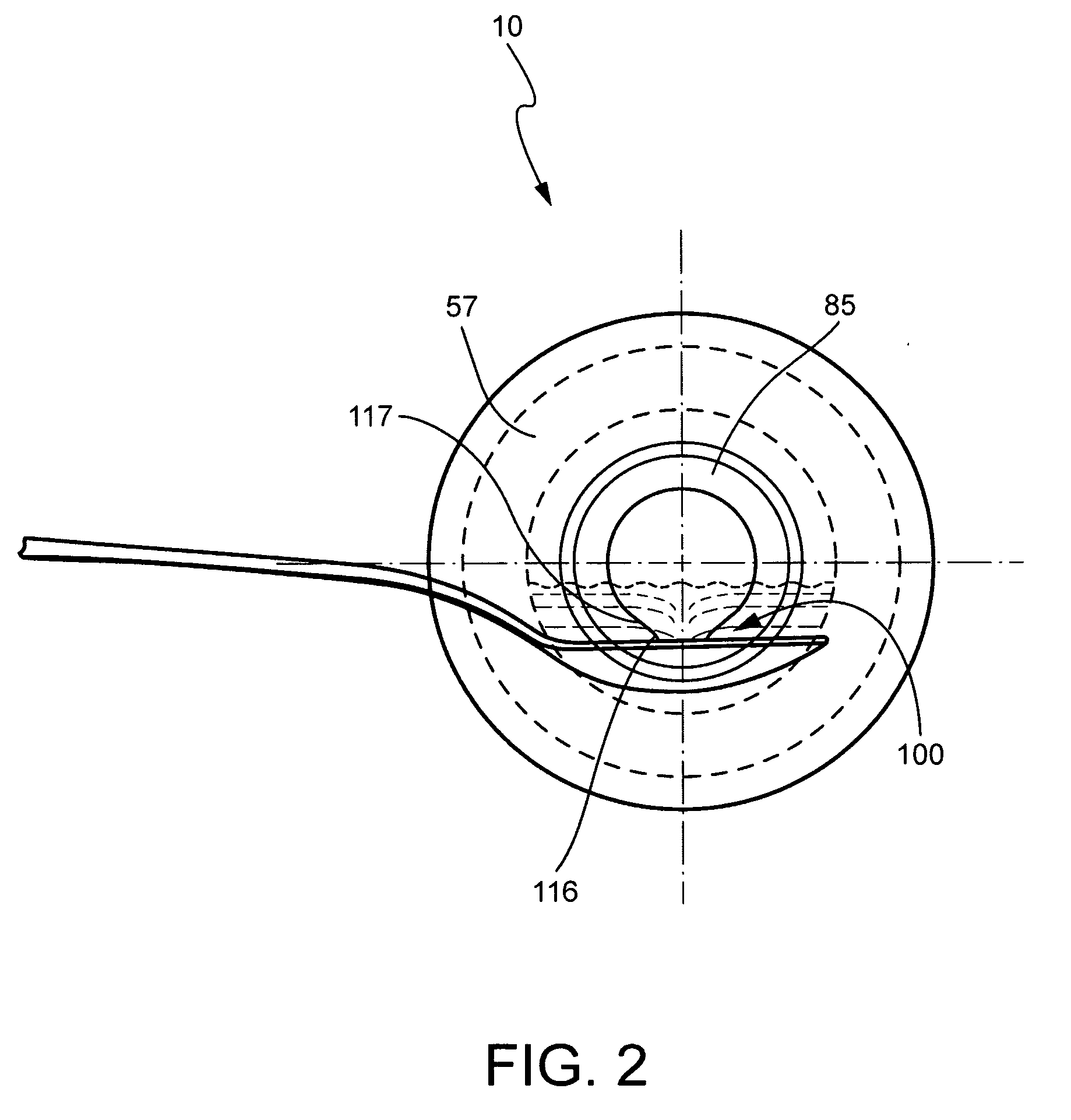
[0066]Referring to the embodiment of FIGS. 1 and 2, a vessel 10 is shown, comprising a relatively thick body wall 16 defining a body 17, and a thinner mouth wall 21 defining a mouth 22.

[0067]The body wall 16 comprises a tubular portion 50 and a base 55. The tubular portion 50 takes the form of a cylinder with an open bottom end 56 and a closed top end 57. A central aperture is located in the top end 57 forming a throat 60. The throat 60 is gradually curved where it opens at a bottom surface 61 of the top end 57. In another embodiment, the throat 60 is chamfered where it open...


PUM


Abstract

The disclosure relates to a vessel for holding fluid. The vessel has at least one wall defining a mouth, the mouth having an inner surface, an outer surface, an end surface and one or more spouts located at the junction of the inner and end surfaces. At least one of the one or more spouts comprises a recess in the inner surface and an outlet at the end surface, the recess being shaped to transition smoothly from the inner surface to the outlet. The disclosure also relates to a vessel and lid assembly and a pouring attachment for a bottle having the mouth as described above.

Description

FIELD OF THE INVENTION[0001]The present invention relates to a vessel for holding and dispensing fluid.[0002]The invention has been developed primarily for use in the pharmaceutical and food industries; for example, for holding and dispensing liquid medication and liquid ingredients respectively and will be described hereinafter with reference to these applications. However, it will be appreciated that the invention is not limited to these particular fields of use; for example, it may be used in any industrial, domestic or commercial industries in which fluids need to be dispensed accurately or without spillage; for example, the vessels may be used to hold and dispense engine oil, water, milk, paints or dyes.BACKGROUND OF THE INVENTION[0003]Fluids are usually stored in vessels such as vials, bottles, containers, jugs, kettles, decanters and buckets.[0004]In the pharmaceutical industry or food industry, liquid medication or liquid ingredients are often sold in small glass or plastic ...

Claims


Application Information

Patent Timeline
IPC IPC(8): B65D5/72
CPCB65D1/023B65D23/06B65D23/04
Inventor ENAHORO, HENRY
Owner ENAHORO HENRY
Why Eureka
Try Eureka