
Noncontact power transmission system and power transmitting device

a power transmission system and non-contact technology, applied in the direction of switch power arrangement, contact mechanism, relay, etc., can solve the problem of increasing power consumption on standby, and achieve the effect of reducing power consumption and shortening the time of feeding a primary coil

Active Publication Date: 2008-09-25
SEIKO EPSON CORP
View PDF6 Cites 90 Cited by
  • Summary
  • Abstract
  • Description
  • Claims
  • Application Information

AI Technical Summary

Benefits of technology

[0023]The present invention having such a configuration can shorten time of feeding a primary coil in intermittently operating a power transmitting device and can reduce power consumption in the power transmitting device on standby.

Problems solved by technology

Accordingly, the power transmitting device needs to supply power to the primary coil during the predetermined time T1 until the power receiving device is ready to respond, and there is a problem of power consumption that increases on standby as the predetermined time T1 increases, which requires a solution thereto.

Method used


Image

  • Noncontact power transmission system and power transmitting device
  • Noncontact power transmission system and power transmitting device
  • Noncontact power transmission system and power transmitting device

Examples


Embodiment Construction

[0031]Embodiments of the present invention will be more particularly described with reference to the accompanying drawings.

[0032]Prior to description of embodiments of the present invention, description will be made on a brief summary of the present invention and a basic concept thereof.

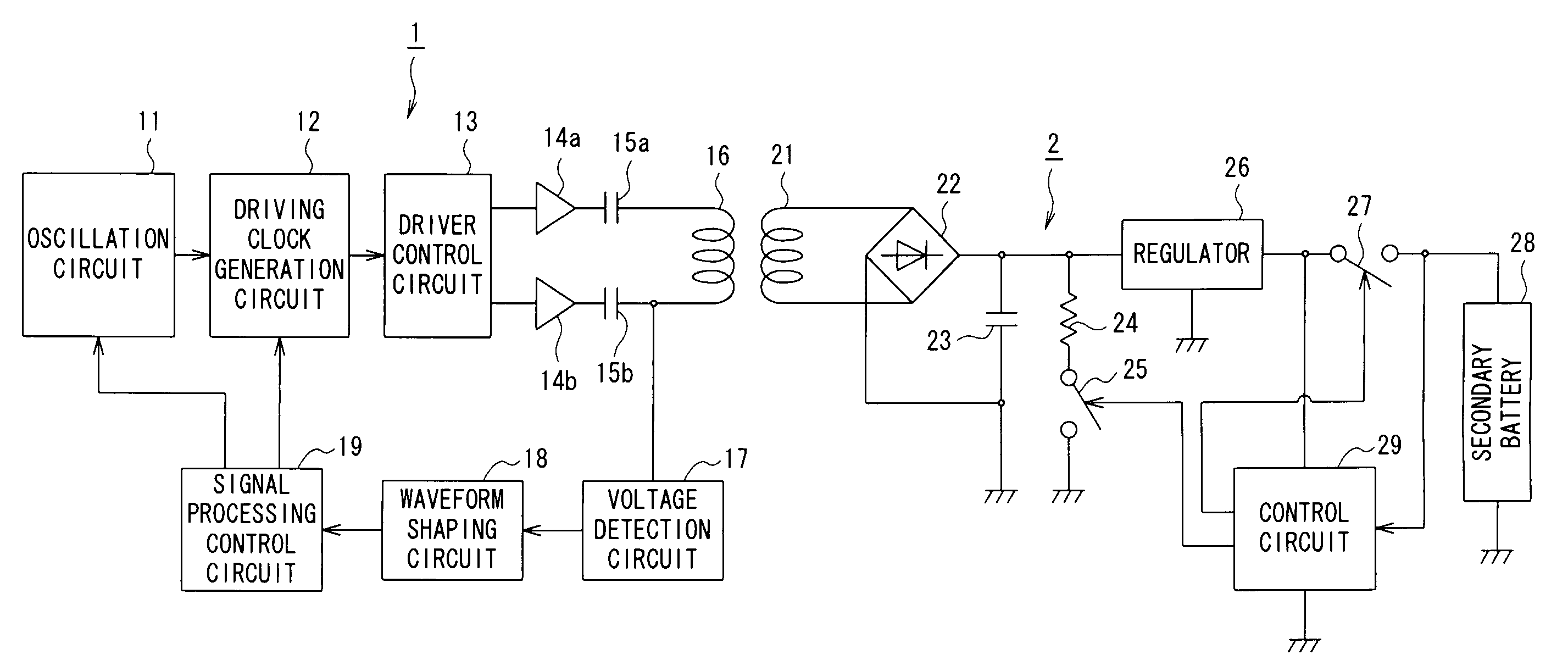
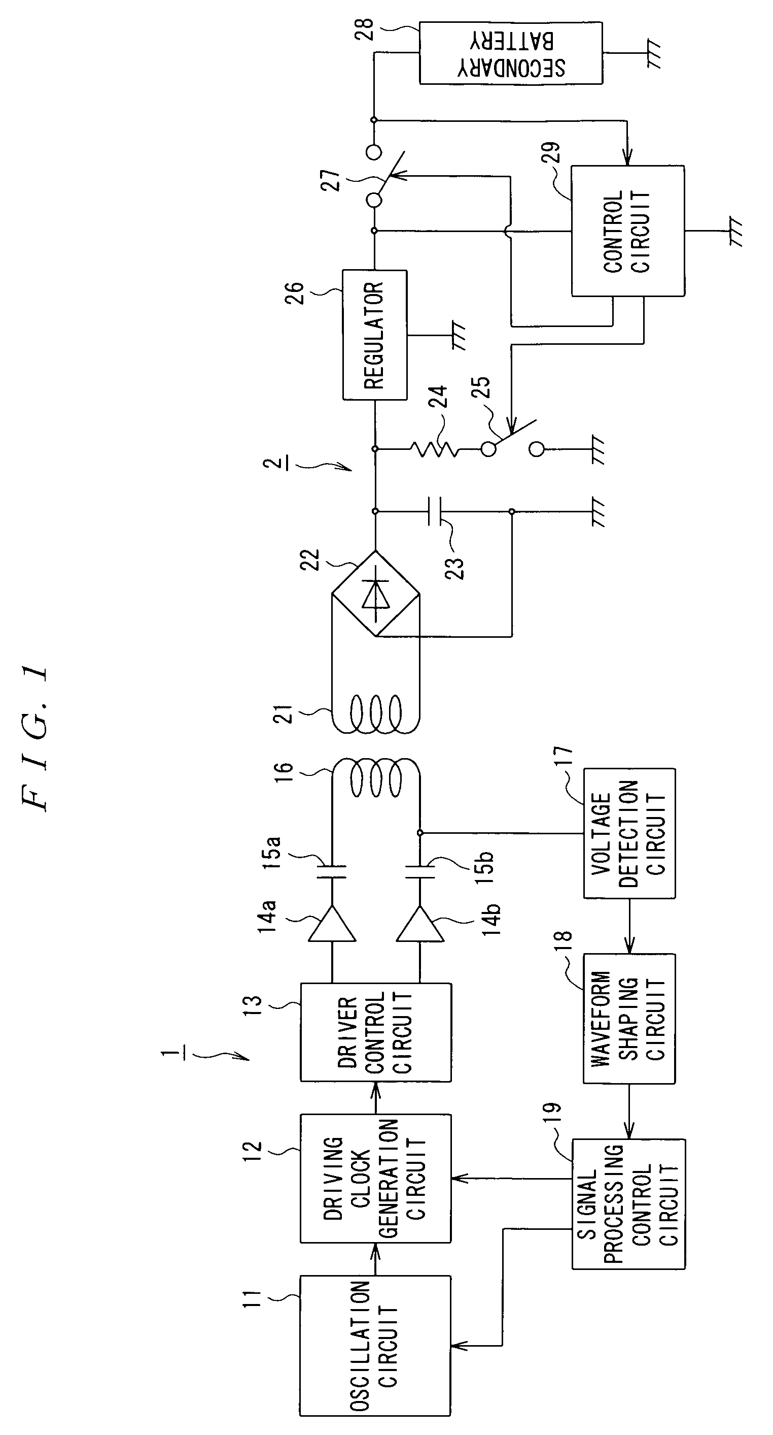
[0033]A noncontact power transmission system according to the present invention is installed (applied), for example, in a mobile phone and, as illustrated in FIG. 1, and is adapted to contactlessly transmit electric power from a transmitting device 1 on the primary side to a power receiving device 2 on the secondary side, utilizing electromagnetic induction.

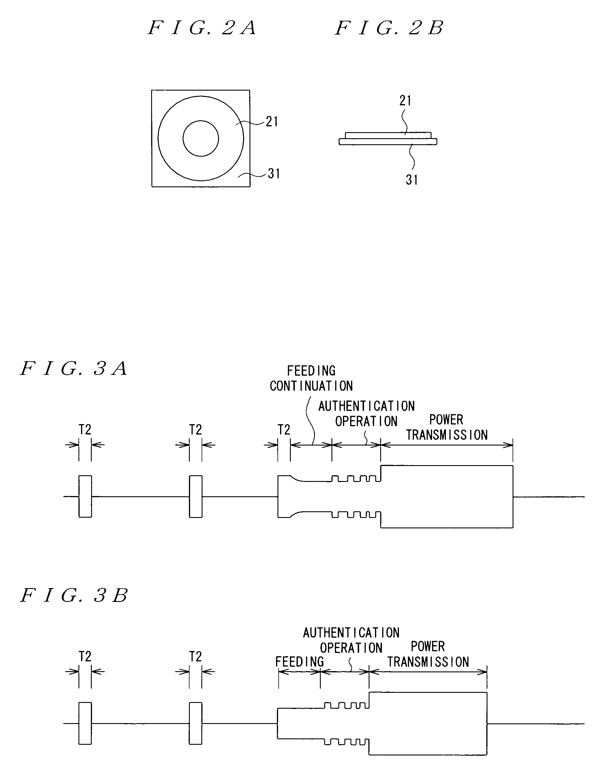
[0034]The present invention has focused attention on a fact that when a secondary coil 21 provided with a magnetic substance 31 on the power receiving device 2 side is in proximity to a primary coil 16 of the power transmitting device 1 when and immediately after starting feeding to the primary coil 16, a self inductance of the primary coil 16 cha...


PUM


Abstract

A noncontact power transmission system having a power transmitting device including a primary coil and a power receiving device including a secondary coil, the primary coil and the secondary coil being electromagnetically coupled to each other and the power transmitting device configured to transmit electric power to the power receiving device, wherein the secondary coil contains a magnetic substance, the power transmitting device has a feeding section for feeding power to the primary coil and a self inductance detection section for detecting a change in the self inductance of the primary coil immediately after starting the feeding to the primary coil, wherein a feeding operation of the feeding section immediately after starting the feeding is determined based on a detection result of the self inductance detection section.

Description

[0001]The entire disclosure of Japanese Patent Application No. 2007-073256, filed Mar. 20, 2007 is expressly incorporated by reference herein.BACKGROUND OF THE INVENTION[0002]1. Field of the Invention[0003]The present invention relates to a noncontact power transmission system that contactlessly transmits electric power from a power transmitting device on the primary side to a power receiving device on the secondary side using electromagnetic induction.[0004]2. Description of the Related Art[0005]A noncontact power transmission system of this type has conventionally been disclosed in, e.g., JP-A-2006-60909 (hereinafter referred as Patent Document 1).[0006]The noncontact power transmission system described in Patent Document 1 verifies whether or not a power transmitting device and a power receiving device are regular, by means of mutual communication, prior to power transmission and, until completion of the verification, the power transmitting device does not start full-scale power ...

Claims


Application Information

Patent Timeline
Patent Type & Authority Applications(United States)
IPC IPC(8): H02J17/00H02J7/00
CPCH02J7/025H02J5/005H02J7/00045H02J50/12H02J50/80
Inventor JIN, MIKIMOTO
Owner SEIKO EPSON CORP
Learn More