Trigger operated portable electronic device
- Summary
- Abstract
- Description
- Claims
- Application Information
AI Technical Summary
Benefits of technology
Problems solved by technology
Method used
Image
Examples
Example
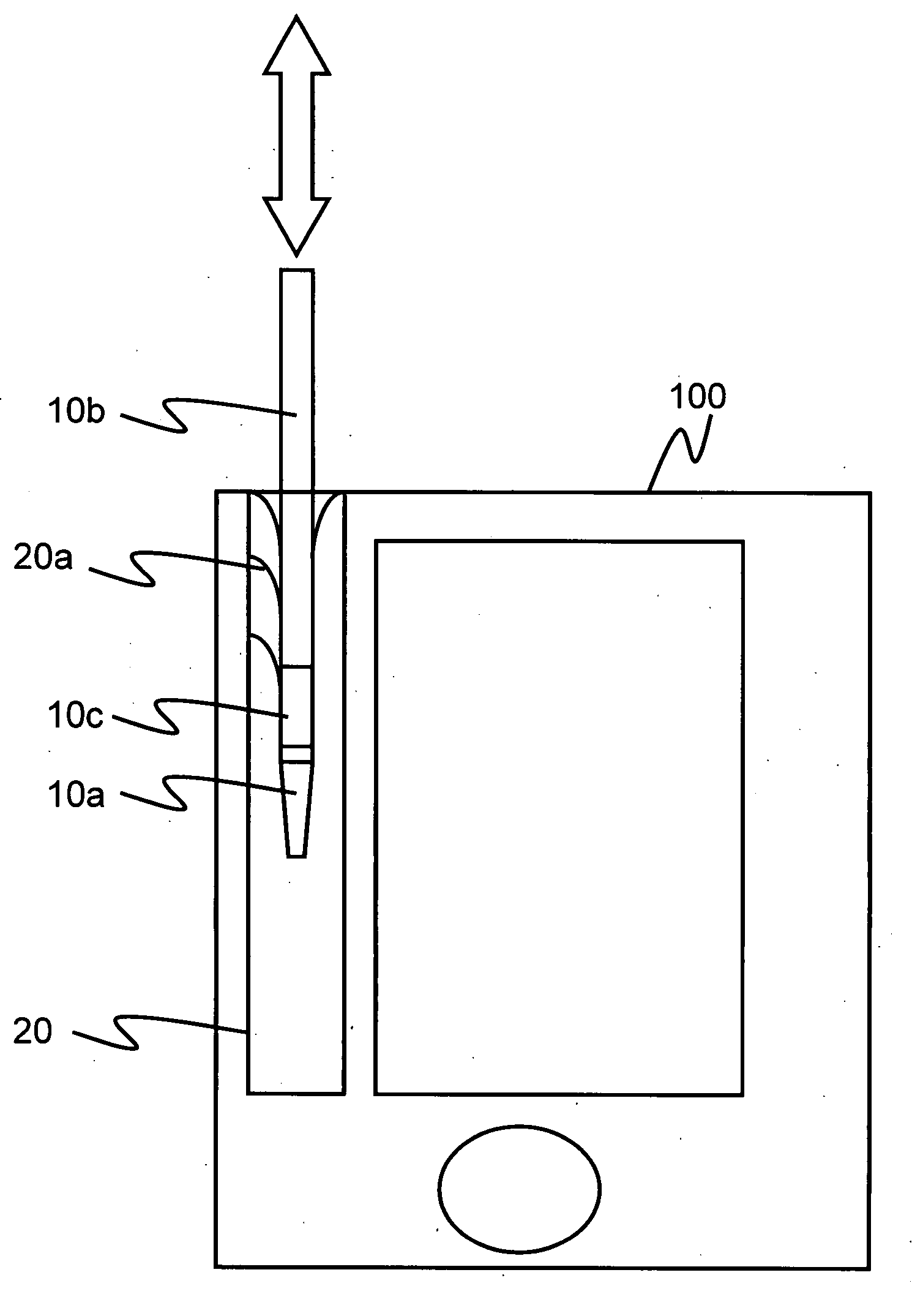
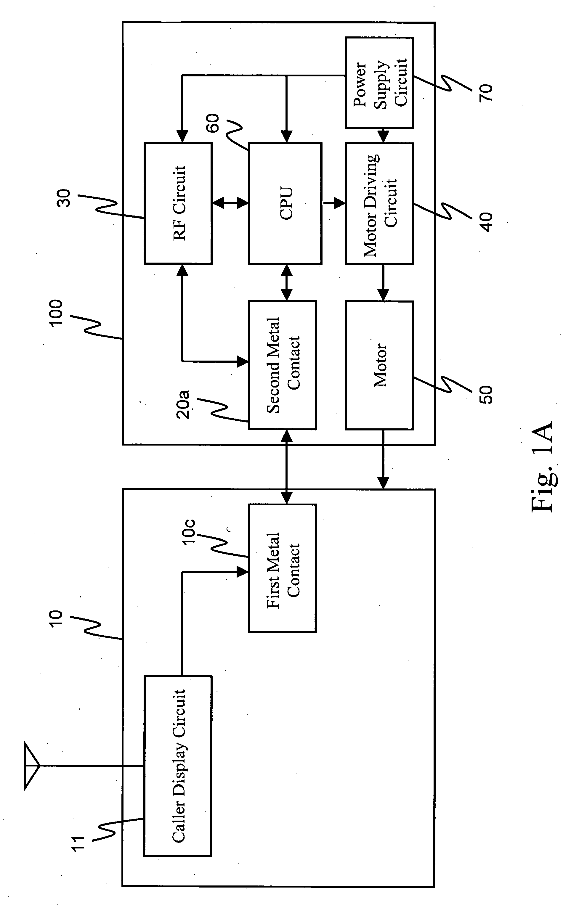
[0016]FIG. 1A is a system block diagram of a first embodiment of the present invention. As shown in FIG. 1A, the trigger operated portable electronic device of the present invention includes a touch pen 10 and a portable electronic device 100.
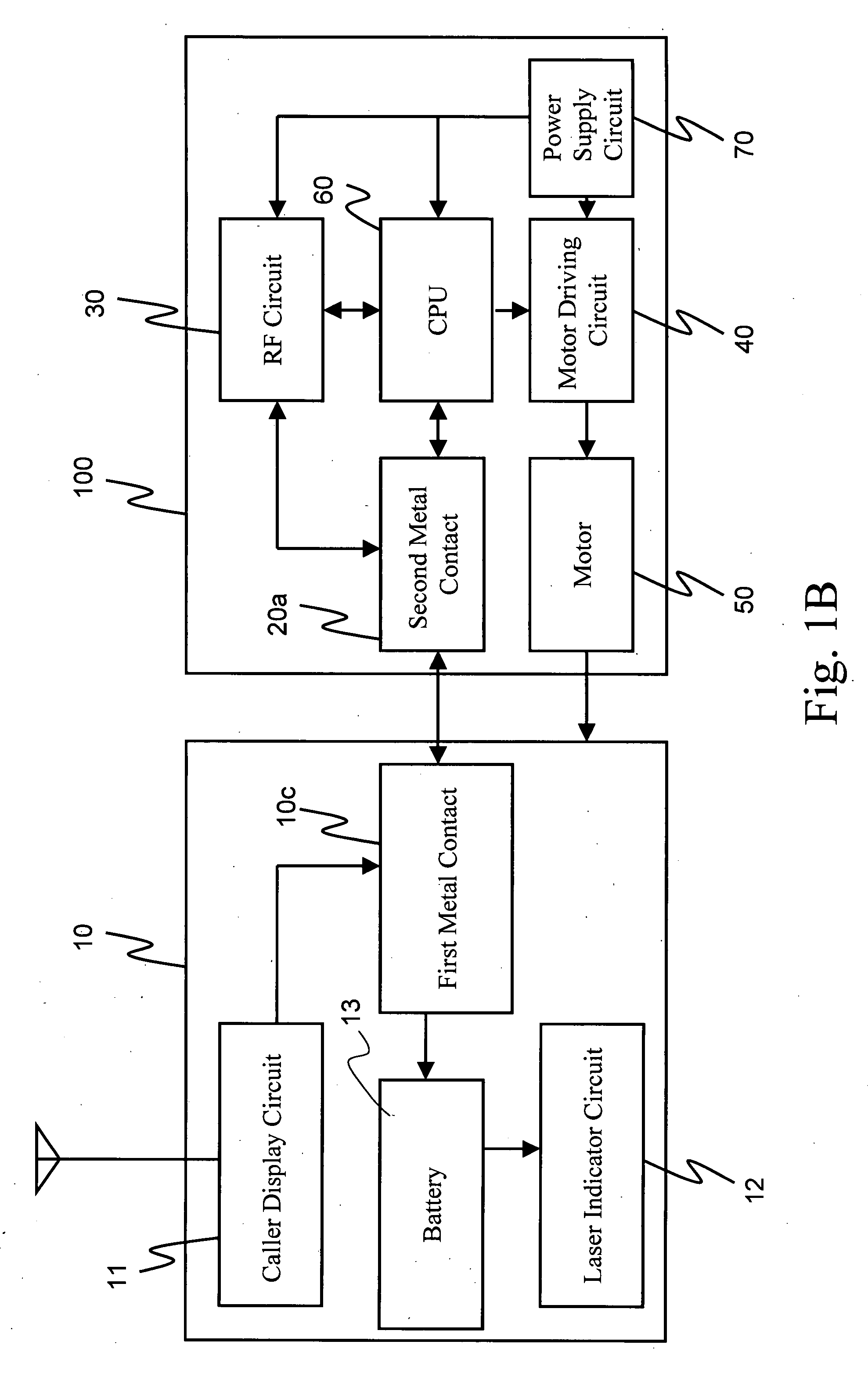
[0017]The touch pen 10 is used to enable a user to operate the portable electronic device 100. A caller display circuit 11 and a first metal contact 10c are disposed in the touch pen 10, and the caller display circuit 11 is electrically coupled to a pen body 10b (as shown in FIG. 2A) of the touch pen 10 and the first metal contact 10c. The pen body 10b of the touch pen 10 is used as an antenna to sense an incoming call signal, and is made of a metal material (for example, copper or iron). When the caller display circuit 11 senses the incoming call signal, a display module (not shown) in the caller display circuit 11 produces a luminous effect, so as to remind the user.
[0018]The portable electronic device 100 includes second metal contacts 20a, ...
Example
[0025]FIG. 1B is a system block diagram of a second embodiment of the present invention. As shown in FIG. 1B, the trigger operated portable electronic device of the present invention includes a touch pen 10 and a portable electronic device 100. The difference between the second embodiment and the first embodiment is that a laser indicator circuit 12 and a battery 13 are disposed in the touch pen 10 of the second embodiment. Other parts of the second embodiment are the same as the first embodiment, and will not be described herein again.
[0026]The laser indicator circuit 12 is electrically coupled to the first metal contact 10c and the battery 13, for emitting a laser indication signal.
[0027]The battery 13 is electrically coupled to the first metal contact 10c and the laser indicator circuit 12 respectively, for providing the electric power required during the operation of the laser indicator circuit 12, and the battery 13 is a rechargeable battery. When the first metal contact 10c is...
Example
[0034]FIG. 2B is a schematic view showing operations of a third embodiment of the present invention. As shown in FIG. 2B, the trigger operated portable electronic device of the present invention includes a touch pen 10, a touch pen receiving slot 20, a sound source output hole 80, and a portable electronic device 100. The difference between the third embodiment and the first embodiment is that metal contacts 80a of the third embodiment are disposed in the sound source output hole 80. Other parts of the third embodiment are the same as the first embodiment, and will not be described herein again.
[0035]The touch pen receiving slot 20 has an accommodation space for accommodating the touch pen 10.
[0036]A plurality of metal contacts 80a is disposed in the sound source output hole 80, and each of the metal contacts 80a at least connects two kinds of circuits. The circuits connected to each of the metal contacts 80a in the sound source output hole 80, for example, can be an earphone sound ...
PUM
Abstract
Description
Claims
Application Information
- R&D Engineer
- R&D Manager
- IP Professional
- Industry Leading Data Capabilities
- Powerful AI technology
- Patent DNA Extraction
Browse by: Latest US Patents, China's latest patents, Technical Efficacy Thesaurus, Application Domain, Technology Topic.
© 2024 PatSnap. All rights reserved.Legal|Privacy policy|Modern Slavery Act Transparency Statement|Sitemap