
Replaceable LED light source device used in backlight module

a led light source and backlight module technology, applied in the direction of lighting and heating apparatus, instruments, mechanical equipment, etc., can solve the problems of difficult to dissipate heat generated during the illumination process, the directivity of light passing through the diffuser bb>31/b> is low, and the source cannot provide enough ligh

Inactive Publication Date: 2008-09-25
PROMATE ELECTRONICS
View PDF13 Cites 69 Cited by
  • Summary
  • Abstract
  • Description
  • Claims
  • Application Information

AI Technical Summary

Benefits of technology

[0009]The primary object of the present invention is to provide a replaceable LED light source device used in a backlight module to replace a LED light source device, which stops working for different reasons during the operation process, without discarding or disassembling and reassembling the whole backlight module which takes much time and labor.

Problems solved by technology

This light source is unable to provide enough light solely by reflecting the ambient light in dark places.
However, the light passing through the diffuser B31 has low directivity.
Thus, the heat generated during the illumination process is difficult to be dissipated and it will result in the high temperature of the backlight module.
Moreover, the LED light source device is disposed within a LED backlight module conventionally, and if the lifetime of the LED expires or the LED stops working for other different reasons during the operation process, the whole backlight module either has to be discarded or has to be disassembled and reassembled with much time and labor.
It is not economic and brings much inconvenience to the users.

Method used


Image

  • Replaceable LED light source device used in backlight module
  • Replaceable LED light source device used in backlight module
  • Replaceable LED light source device used in backlight module

Examples


Embodiment Construction

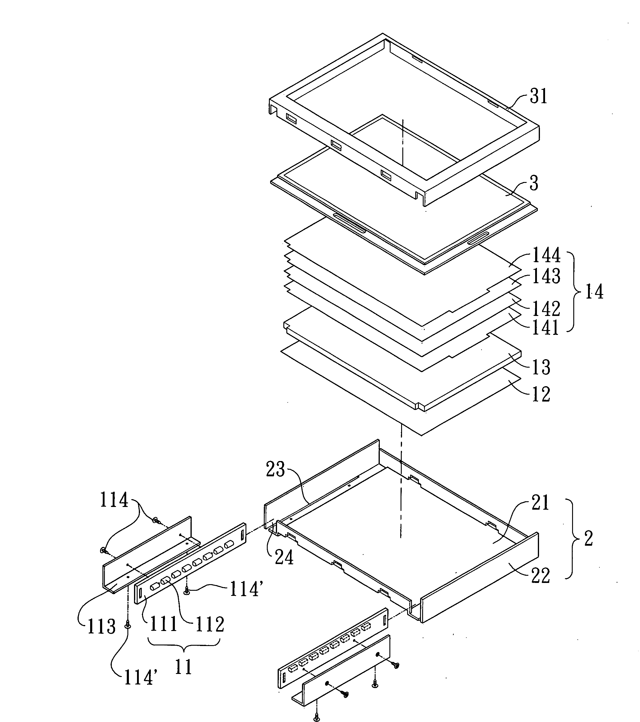
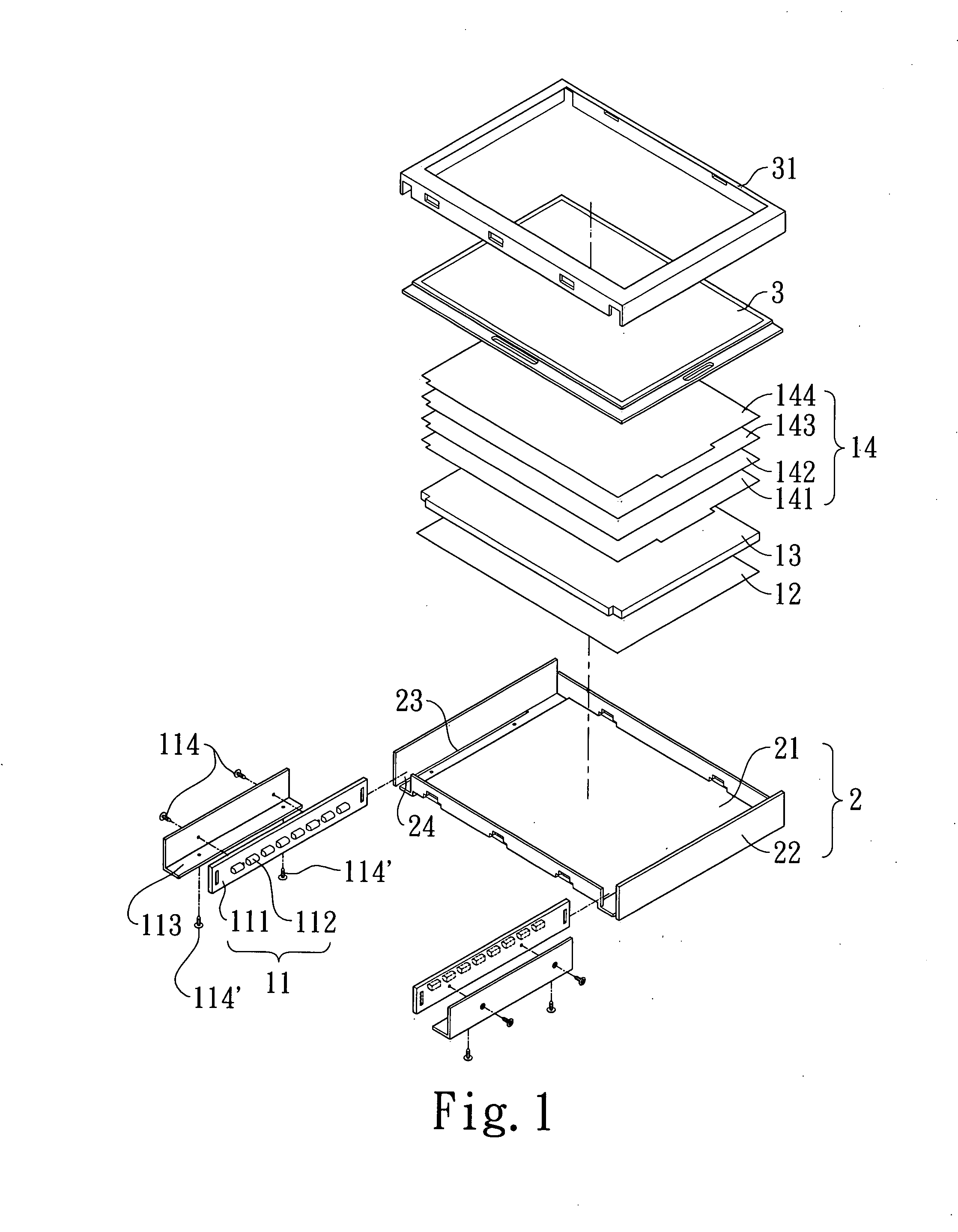
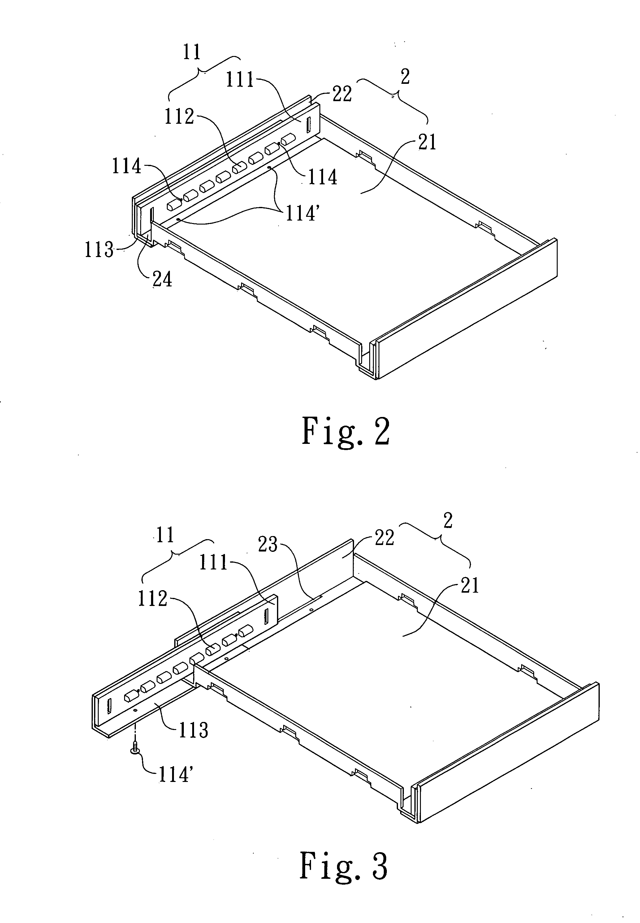
[0018]The present invention provides a replaceable LED light source device 11 used in a backlight module, comprising a detachable LED bar 111 having a plurality of LEDs 112 thereon providing illumination of the backlight module, and an attaching plate 113, 1131 for disposing the detachable LED bar 111 within a case 2 locating the backlight module therein via an aperture 24, 25 on the case 2.

[0019]FIG. 1-3 shows a first embodiment of a replaceable LED light source device 11 used in a LED backlight module according to the present invention, wherein FIG. 1 shows an exploded perspective view of the first embodiment. As shown in FIG. 1, backlight module is placed under a LCD panel 3 with a frame 31 and comprises a LED light source device 11, a reflector 12, a light guiding plate 13, and a pile of optical sheets 14. The backlight module is disposed within a case 2. The LED light source device 11 includes a LED bar 111 and a plurality of LEDs 112 disposed thereon, wherein the LED bar 111 c...


PUM


Abstract

A replaceable LED light source device used in a backlight module comprises a LED bar disposed with a plurality of LEDs thereon used for providing illumination and an attaching plate used for disposing the detachable LED bar within a case locating the backlight module therein. Thereby, the previous LED light source device can be replaced by a new one when any LED on the LED bar stops working.

Description

BACKGROUND OF THE INVENTION[0001]1. Field of the Invention[0002]The present invention relates to a LED light source device used in a backlight module and, more particularly, to a replaceable LED light source device used in a backlight module to substitute the previous light source device where the LEDs of the LED bar stop working.[0003]2. Description of the Prior Art[0004]With the dramatic development of the Internet and the wireless communication technology, information becomes easily accessible to everyone and thereby the personal information-related electronic products, such as notebooks, mobile phones, digital cameras, and personal digital assistants, are rapidly developed and grown. Going with the ascending trend of the market on the Internet digital information, Liquid Crystal Displays (LCD) is developed even faster and becomes thinner, lighter, less energy consumption, safer and able to be incorporated in the semiconductor manufacturing technology. However, a LCD needs extra ...

Claims


Application Information

Patent Timeline
IPC IPC(8): F21V8/00
CPCG02B6/0068G02F2001/133325G02B6/009G02B6/0073G02F1/133325
Inventor WENG, DERCHINLU, HAN-WEI
Owner PROMATE ELECTRONICS
Learn More