Shock-proof electrical wiring system

a technology of electrical wiring and shock-proof, which is applied in the direction of electrical apparatus, connection contact material, coupling device connection, etc., can solve the problems of labor-intensive, time-consuming, and high installation cost of electrical circuits in buildings and/or other structures, and achieves cost-effectiveness, labor-saving and cost-effective, and eliminates many labor-intensive practices

Inactive Publication Date: 2010-05-25
PASS SEYMOUR
View PDF42 Cites 20 Cited by
  • Summary
  • Abstract
  • Description
  • Claims
  • Application Information

AI Technical Summary

Benefits of technology

[0010]The present invention addresses the needs described above by providing an efficient, labor-saving, and cost effective means for terminating the electrical wires and coupling them to the individual devices. The system and method is cost-effective because it eliminates many of the labor intensive practices that are currently in use. The system of the present invention is also shock-proof, in that it prevents children from inserting foreign objects into the face receptacles, trips the device once an end-of-life condition has been reached, and may be safely and easily replaced without the possibility of shock.

Problems solved by technology

Installing electrical circuits in buildings and / or other structures is typically labor intensive, time-consuming, and a process that requires electricians of various skill levels.
As a result the installation process is expensive.
This part of the installation process is the most costly and time consuming.
Because safety is paramount, there are several safety issues that must be considered.
One safety issue that must be considered relates to child-safely and is concerned with preventing the child from inserting foreign objects into the face receptacles.
Another issue relates to safely disabling or tripping the device once an end-of-life condition has been reached.
Yet another issue relates to safely replacing the wiring device once end-of-life has been reached.

Method used


Image

  • Shock-proof electrical wiring system
  • Shock-proof electrical wiring system
  • Shock-proof electrical wiring system

Examples


first embodiment

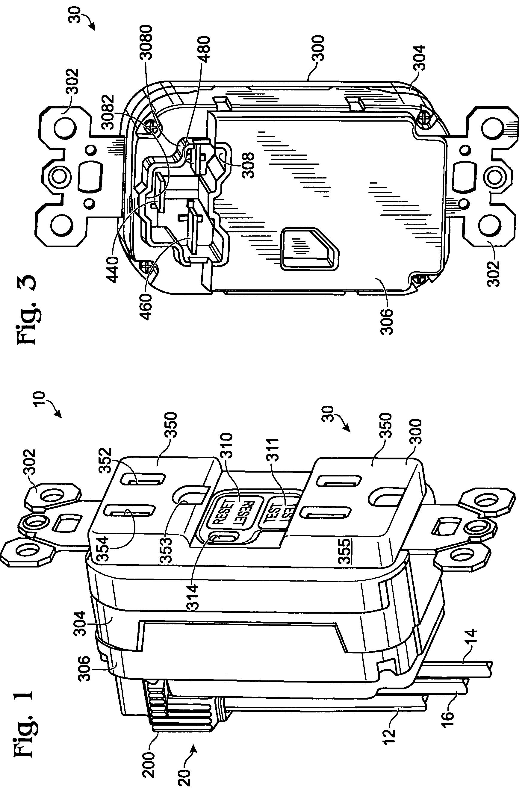
[0032]As embodied herein, and depicted in FIG. 1, a perspective view of an electrical wiring system 10 in accordance with the present invention is disclosed. System 10 includes a plug connector 20 that mates with electrical wiring device 30. Electrical power conductor wires (12,14,16) are terminated by plug contacts disposed within plug housing 200. When plug 20 is installed in device 30, electrical continuity is established between the plurality of wires (12,14,16) and the wiring device 30. One feature of the present invention is that it includes no external terminal connections. Power is provided to device 30 via plug connector 20. Service, depending on the nature of the device, is provided to the user via the front face. The present invention may be configured to accommodate 2 wire systems and three-phase (5 wire) systems, as well as the 3-wire system shown. Further, system 10 of the present invention may be adapted to a wiring system that employs more than 5 wires.

[0033]The exte...

third embodiment

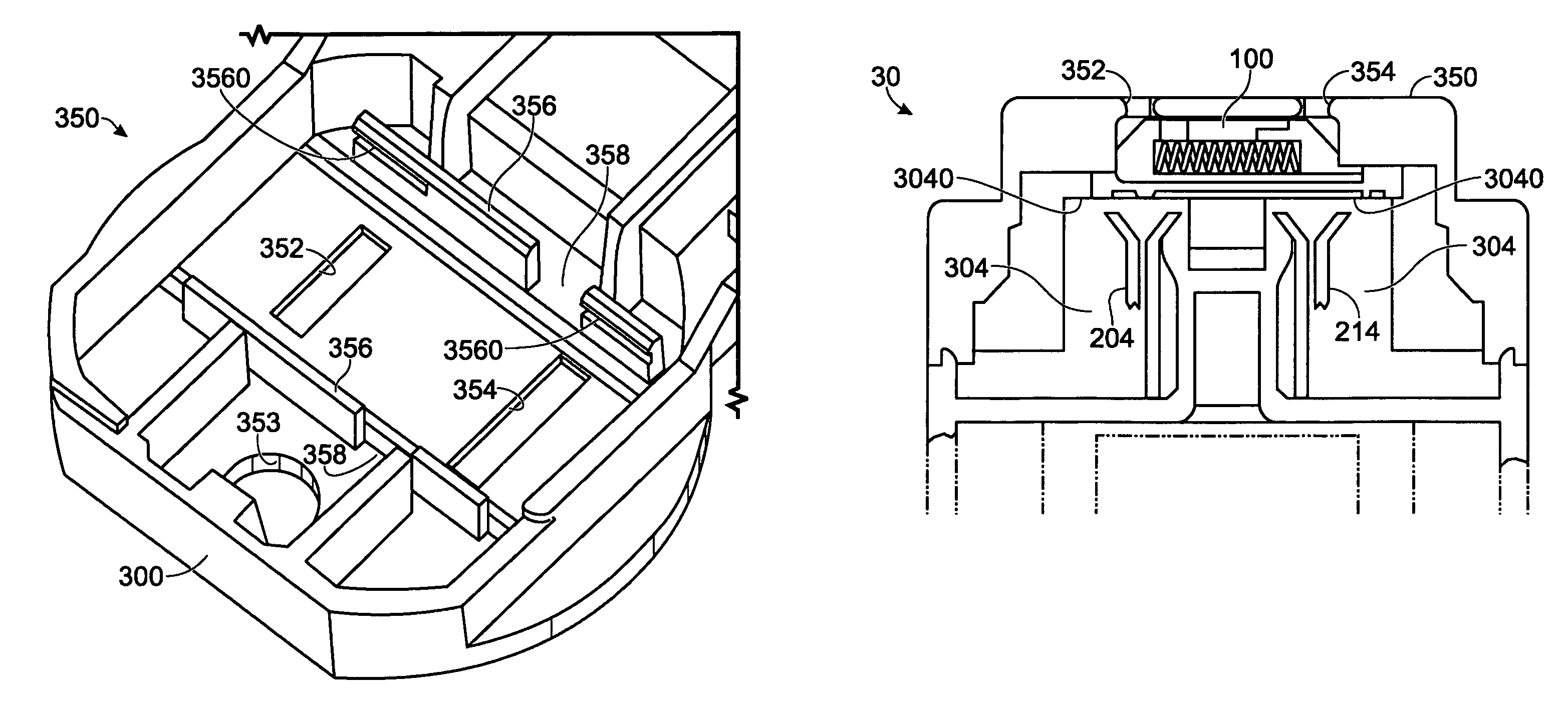
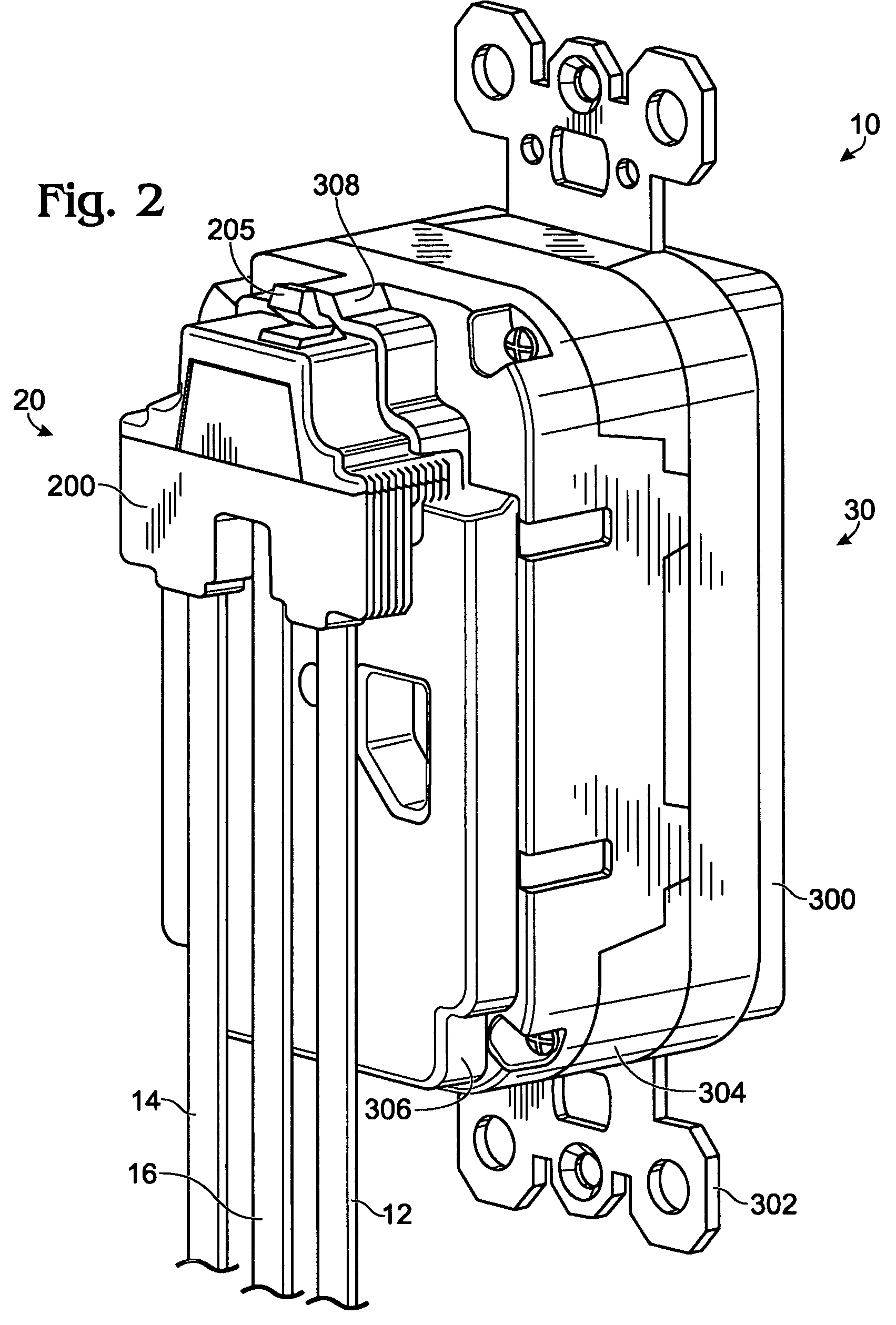
[0072]As embodied herein and depicted in FIG. 11, a perspective view of an electrical wiring system 10 in accordance with the present invention is disclosed. The wiring device 30 is identical to the device depicted in FIG. 1 and described herein. Note that Receptacle 308 is shaped to accommodate both plug connector 20 embodiments. As before, receptacle 308 includes hot line receptacle blade 460, neutral line receptacle blade 480, and ground receptacle blade 440. Of course, each male contact blade (440, 460, 480) mates with a corresponding female contact mechanism in plug connector 20.

[0073]Like the previous embodiment, plug connector 20 aligns the conductors (12,14,16) with the contacts disposed therein. What is different from the previous embodiment is the 180° configuration, i.e., conductors (12,14,16) and the internal plug contacts are arranged, substantially, in a 180° angle. Housing 200 includes latch mechanism 205. When plug connector 20 is inserted into receptacle 308, latch ...

second embodiment

[0078]As embodied herein and depicted in FIG. 12, a bottom perspective view of an electrical wiring device 30 in accordance with the present invention is disclosed. This embodiment features a cowled external rear receptacle 308 that may be employed with the plug connector 20 shown in FIG. 11. Receptacle 308 includes a raised portion that is configured to accommodate the latch 205. Comparing FIG. 12 with FIG. 4, the electrical wiring device is functionally identical, the difference being the cowled external rear receptacle 308 and the mechanical configuration of the rear receptacle blades (440,460, 480) disposed therein.

[0079]As embodied herein and depicted in FIG. 13, GFCI / Light combination device 1100 is disclosed. The electrical wiring device 1100 includes a cover member 300 coupled to a rear body portion 306. The form factor of rear body member 306 is substantially identical to the rear portion 306 of the wiring device depicted in FIGS. 1-12. Wiring device 300 includes a GFCI cir...


PUM


Abstract

A shock-proof electrical wiring system includes a connector device having a connector housing. A plurality of connector contacts are disposed substantially inaccessible to a user within the connector housing. The plurality of connector electrical contacts are connected to a termination arrangement. The termination arrangement is configured to be connected to the portion of the plurality of AC electric power transmitting wires. An electrical wiring device includes a housing assembly that has at least one set of user-accessible receptacle openings disposed in a front major surface thereof in operative alignment with at least one shutter assembly configured to move from a closed position to an open position only in response to engaging a set of plug blades.

Description

CROSS-REFERENCE TO RELATED APPLICATIONS[0001]This application is a continuation-in-part application of U.S. patent application Ser. No. 11 / 691,116 filed on Mar. 26, 2007, now U.S. Pat. No. 7,470,145 which is a continuation of U.S. patent application Ser. No. 11 / 357,563 filed on Feb. 17, 2006, now U.S. Pat. No. 7,195,517 which is a continuation of U.S. patent application Ser. Ser. No. 11 / 032,420 filed on Jan. 10, 2005, now U.S. Pat. No. 7,189,110 which is a continuation-in-part of U.S. patent application Ser. No. 10 / 680,797 filed on Oct. 7, 2003 now U.S. Pat. No. 6,994,585. This application is also a continuation-in-part application of U.S. patent application Ser. No. 11 / 933,928 filed on Nov. 1, 2007, now U.S. Pat. No. 7,642,457 which is a continuation of U.S. patent application Ser. No. 11 / 609,793 filed on Dec. 12, 2006, now U.S. Pat. No. 7,312,394 which is a continuation-in-part of U.S. patent application Ser. No. 10 / 900,778 filed on Jul. 28, 2004, now U.S. Pat. No. 7,179,992 which...

Claims


Application Information

Patent Timeline
Patent Type & Authority Patents(United States)
IPC IPC(8): H01R13/60
CPCH01R13/4534H01R13/665H01R25/003H01R13/7135H01R13/6683H01R13/717
Inventor BENOIT, JOHNSAVICKI, JR., GERALD R.WEEKS, RICHARD
Owner PASS SEYMOUR
Why Eureka
Try Eureka