Mono-block type optical fiber adapter

a monoblock type, optical fiber technology, applied in the field of optical fiber technology, can solve the problems of increased labor cost, increased inconvenience and difficulty in mold design, and increased difficulty in dimensional tolerance and clearan

Active Publication Date: 2014-05-29
CORNING OPTICAL COMM LLC
View PDF9 Cites 20 Cited by
  • Summary
  • Abstract
  • Description
  • Claims
  • Application Information

AI Technical Summary

Benefits of technology

[0013]The present invention has been accomplished under the circumstances in view. It is therefore the main object of the present invention to provide a mono-block type mono-block type optical fiber adapter, which eliminates the drawbacks of the aforesaid prior art designs.
[0014]To achieve this and other objects of the present invention, a mono-block type mono-block type optical fiber adapter of the present invention comprises an adapter body that comprises a partition wall between each two opposing accommodation chambers and a tubular coupling portion extended from each partition wall toward the inside of one respective front-sided accommodation chamber, a ferrule mounted in each tubular coupling portion and partially suspending in the respective rear-sided accommodation chamber, and a ferrule holder respectively mounted in each rear-sided accommodation chamber and attached to the suspended rear end of the respective ferrule. The one piece design of the adapter body facilitates mass production and effectively eliminates the dimensional tolerance and clearance problems of conventional designs. Further, the matching design between the adapter body and the ferrule holders facilitates quick and accurate installation of the mono-block type optical fiber adapter, saving much installation time and labor and enhancing structural stability and reliability.
[0016]The mono-block type optical fiber adapter further comprises a positioning member fastened to the adapter body for securing the adapter body to an external equipment. The adapter body and the positioning member are preferably made out of metal so that the mono-block type optical fiber adapter can provides an excellent EMI (electromagnetic interference) and RFI (radio frequency interference) shielding effect to effectively suppress the energy of electromagnetic waves or radio frequency that passes through the adapter body into the inside of the housing of the optical fiber equipment in which the mono-block type optical fiber adapter is installed and to prevent interference between electronic components in the housing of the optical fiber equipment, improving optical signal transmission quality and reliability.

Problems solved by technology

In consequence, the level of inconvenience and difficulty in designing the molds is relatively increased.
During installation of this prior art design, dimensional tolerance and clearance problems may occur.
Further, this prior art design does not facilitate mass production, resulting in increased labor cost.
If the body shell D is made out of metal, the ferrule holder F can conveniently and accurately mounted in the locating groove D13 inside the body shell D. However, if the body shell D is made out of plastics, frequently plugging and unplugging mating optical fiber connectors can cause loosening or displacement of the ferrule holder F, lowering structural stability and optical fiber connector positioning accuracy.
Thus, plugging optical fiber connectors into the ferrules E or unplugging optical fiber connectors from the ferrules E does not generate any drag force or pulling force to the ferrule holder F to cause loosening or displacement of the ferrule holder F. However, because this prior art design of optical fiber adapter is formed of multiple component parts, it has a complicated structure that does not facilitate mass production.
Further, the installation of this prior art design of optical fiber adapter requires much labor and time.

Method used


Image

  • Mono-block type optical fiber adapter
  • Mono-block type optical fiber adapter
  • Mono-block type optical fiber adapter

Examples


Embodiment Construction

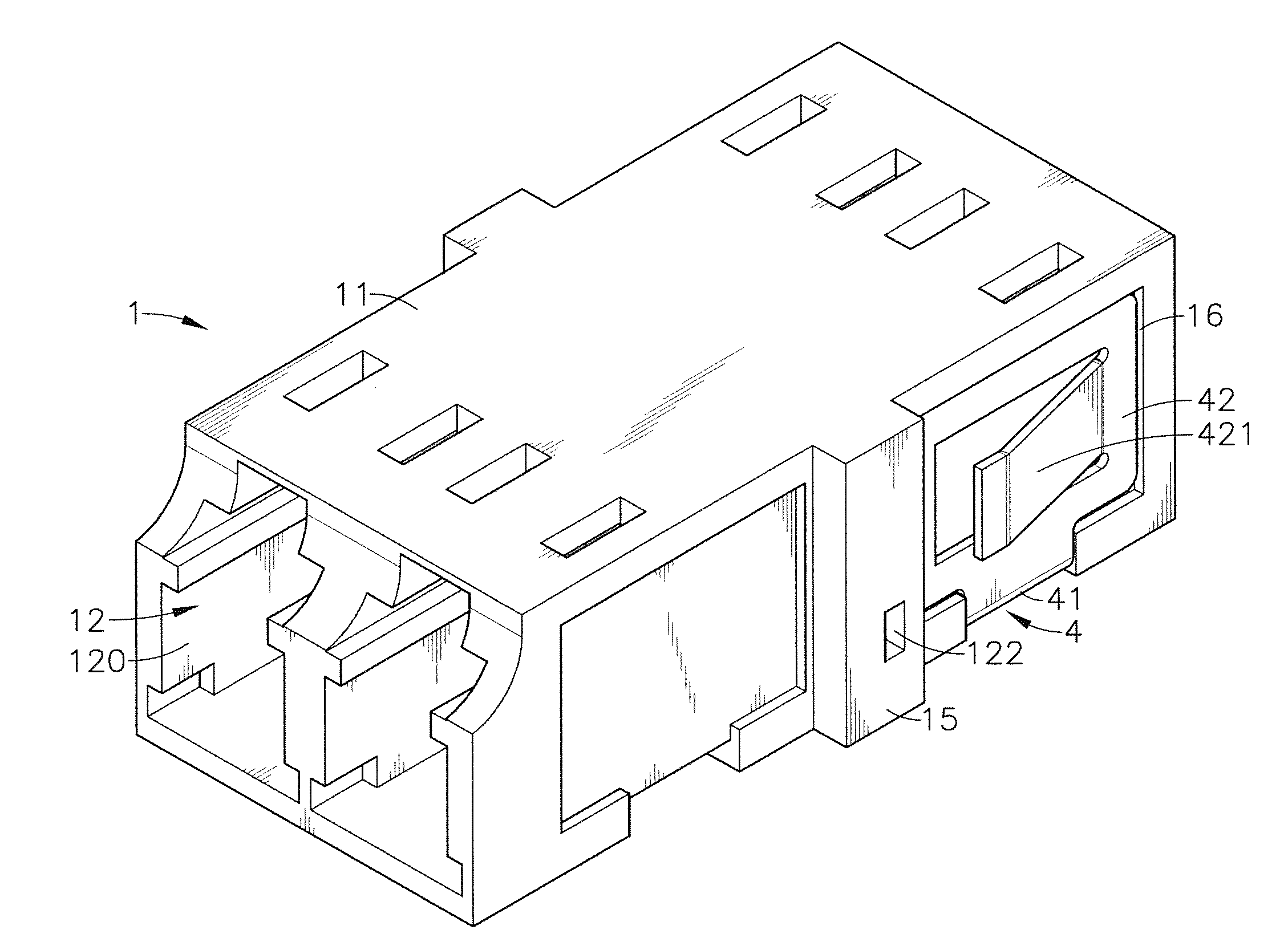
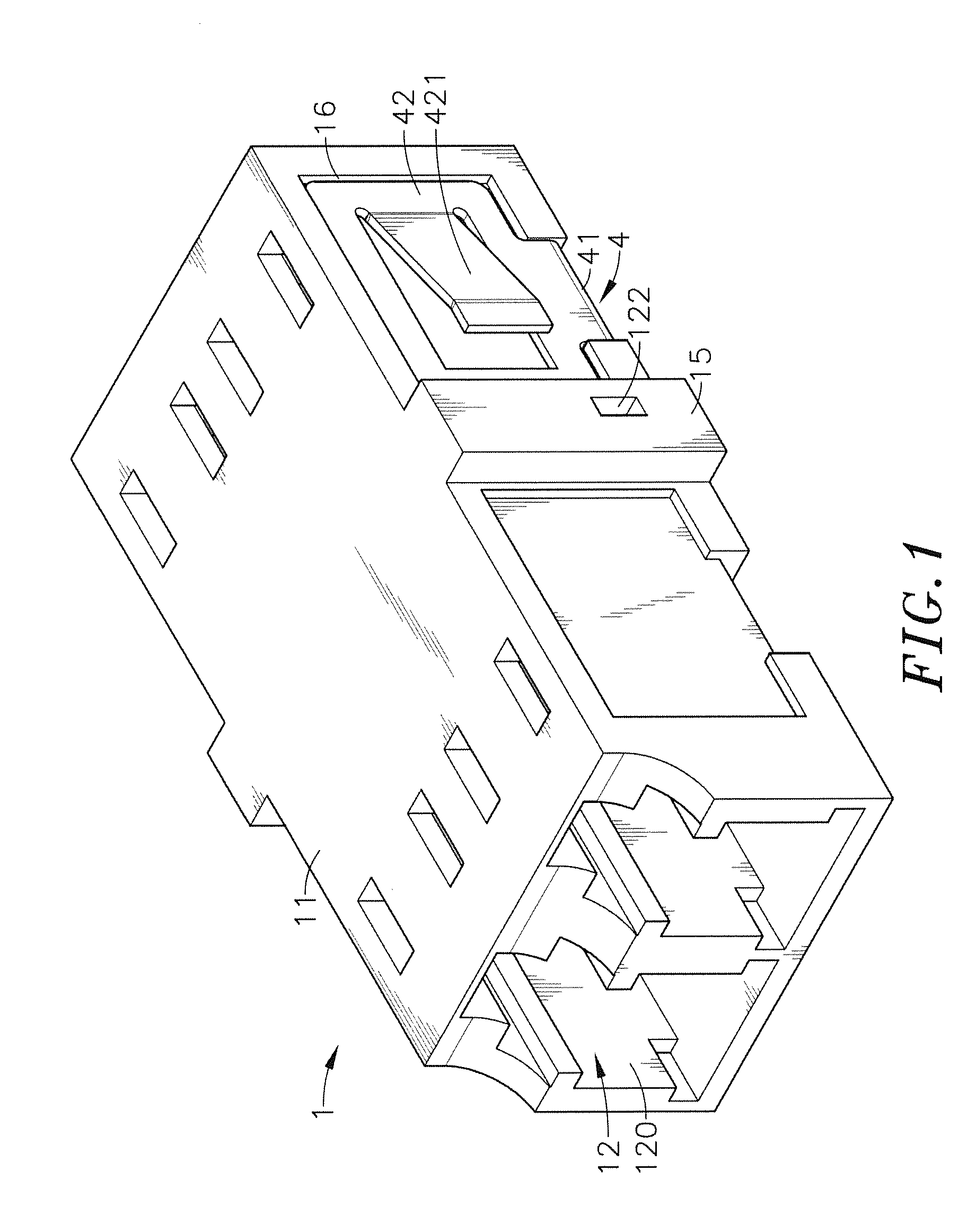
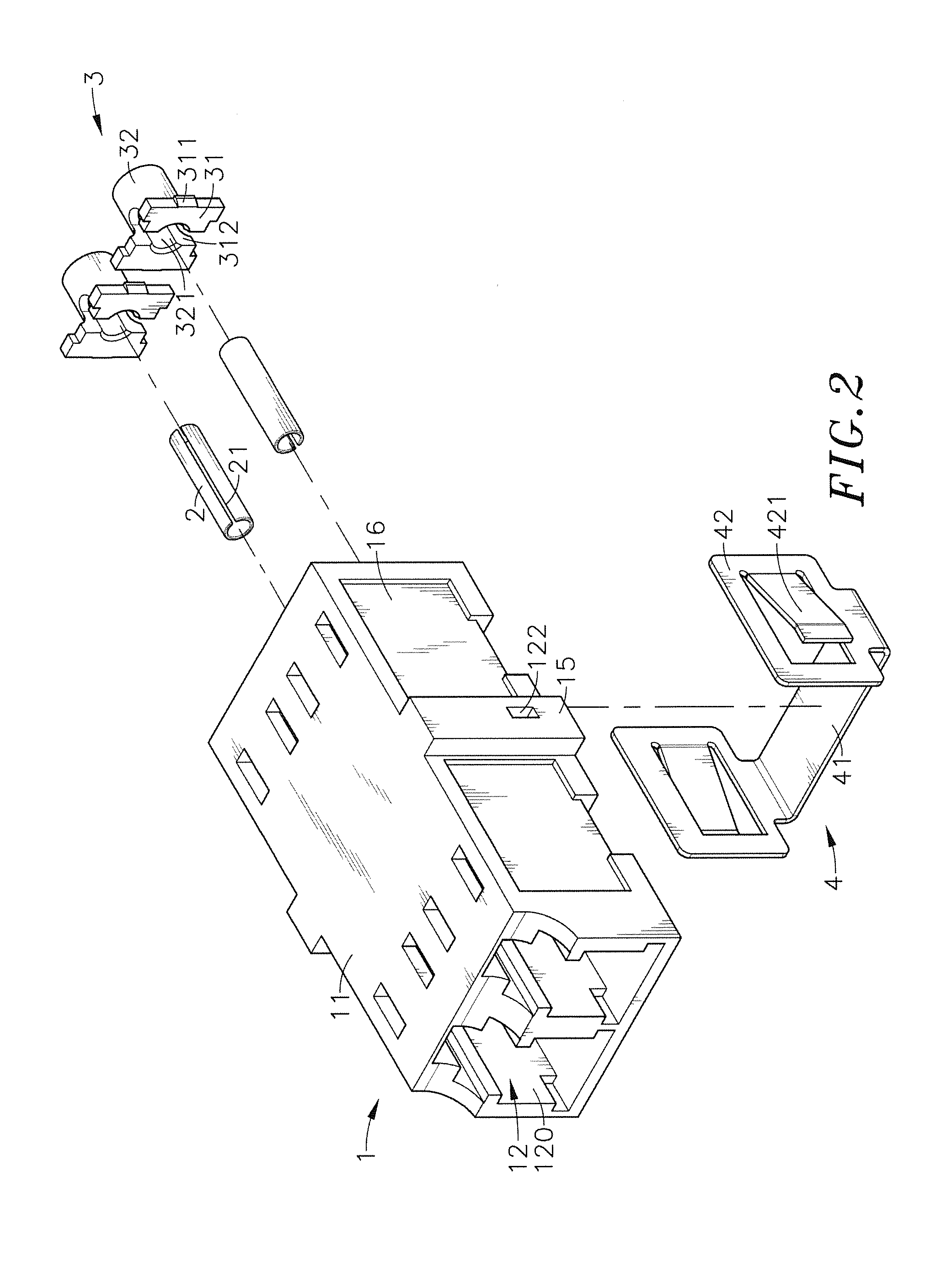
[0038]Referring to FIGS. 1-4, a mono-block type optical fiber adapter in accordance with a first embodiment of the present invention is shown. The mono-block type optical fiber adapter comprises an adapter body 1, a plurality of ferrules 2, a plurality of ferrule holders 3, and a positioning member 4.

[0039]The adapter body 1 comprises a body shell 11, at least one, for example, two pairs of opposing accommodation chambers 12 (i.e., one front-sided accommodation chamber and one rear-sided accommodation chamber) respectively defined in opposing front and rear sides of the body shell 11, a partition wall 13 defined inside the body shell 11 between the two opposing accommodation chambers 12 of each one same pair, an insertion hole 120 disposed in communication between each accommodation chamber 12 and the surroundings, a tubular coupling portion 14 extended from each partition wall 13 toward the inside of one respective front-sided accommodation chamber 12 and defining therein an axiall...


PUM


Abstract

A mono-block type optical fiber adapter includes an adapter body including a partition wall between each two opposing accommodation chambers and a tubular coupling portion extended from each partition wall toward the inside of one respective front-sided accommodation chamber, a ferrule mounted in each tubular coupling portion and partially suspending in the respective rear-sided accommodation chamber, and a ferrule holder respectively mounted in each rear-sided accommodation chamber and attached to the suspended rear end of the respective ferrule. The one piece design of the adapter body facilitates mass production and effectively eliminates the dimensional tolerance and clearance problems of conventional designs. Further, the matching design between the adapter body and the ferrule holders facilitates quick and accurate installation of the mono-block type optical fiber adapter, saving much installation time and labor and enhancing structural stability and reliability.

Description

[0001]This reference is based on Provisional Application Ser. No. 61 / 796,843, filed 23 Nov. 2012, currently pending.BACKGROUND OF THE INVENTION[0002]1. Field of the Invention[0003]The present invention relates to optical fiber technology, and more particularly to a mono-block type mono-block type optical fiber adapter, which comprises an adapter body that comprises a partition wall between each two opposing accommodation chambers and a tubular coupling portion extended from each partition wall toward the inside of one respective front-sided accommodation chamber, a ferrule mounted in each tubular coupling portion and partially suspending in the respective rear-sided accommodation chamber, and a ferrule holder respectively mounted in each rear-sided accommodation chamber and attached to the suspended rear end of the respective ferrule.[0004]2. Description of the Related Art[0005]Following fast development of communication and internet technology, telephone and network facilities are ...

Claims


Application Information

Patent Timeline
Patent Type & Authority Applications(United States)
IPC IPC(8): G02B6/38
CPCG02B6/3825
Inventor LEE, WEI-CHENG
Owner CORNING OPTICAL COMM LLC
Why Eureka
Try Eureka