Image forming apparatus

a technology of image forming apparatus and forming plate, which is applied in the direction of electrographic process apparatus, instruments, optics, etc., can solve the problems of inability to meet the needs of the user, the amount of electric charge of the developer becomes unstable, and the concentration variation of the image formed on the recording plate, so as to reduce heat generation and prevent the concentration variation of the image. , the effect of reducing the cost or siz

Inactive Publication Date: 2008-09-25
KYOCERA DOCUMENT SOLUTIONS INC
View PDF2 Cites 6 Cited by
  • Summary
  • Abstract
  • Description
  • Claims
  • Application Information

AI Technical Summary

Benefits of technology

[0009]An object of the present invention is to provide an image forming apparatus that can prevent concentration variation occurring in an image and reduce heat generation without increase in cost or size.

Problems solved by technology

If the developer is left on the developer carrier for a long time, the amount of electric charge of the developer becomes unstable, and this causes concentration variation in the toner image in the circumferential direction of the photoconductive drum.
This results in concentration variation in an image formed on the recording paper.
This results in inconveniences of size increase and cost increase of the image forming apparatus.

Method used


Image

  • Image forming apparatus
  • Image forming apparatus
  • Image forming apparatus

Examples


Embodiment Construction

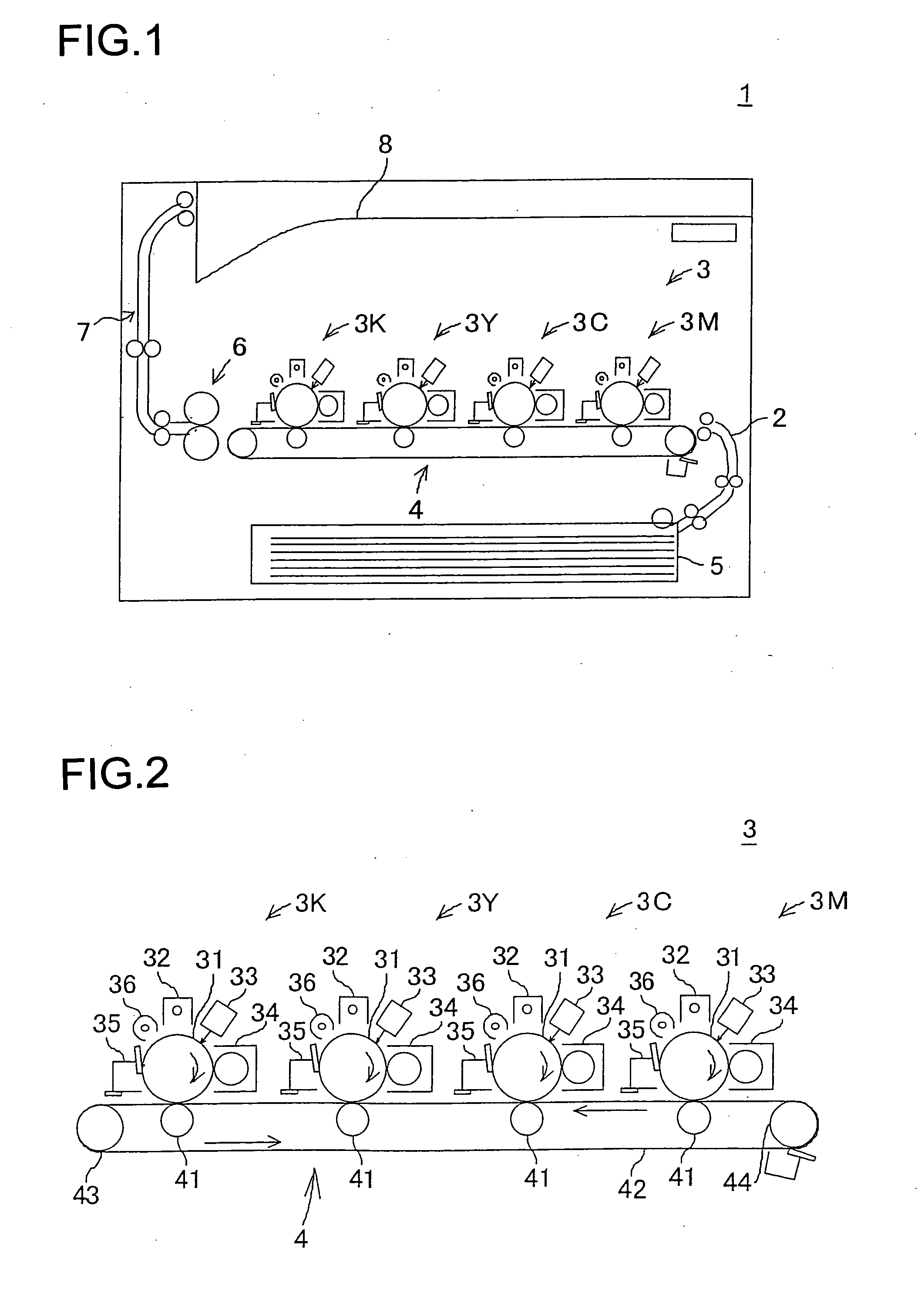
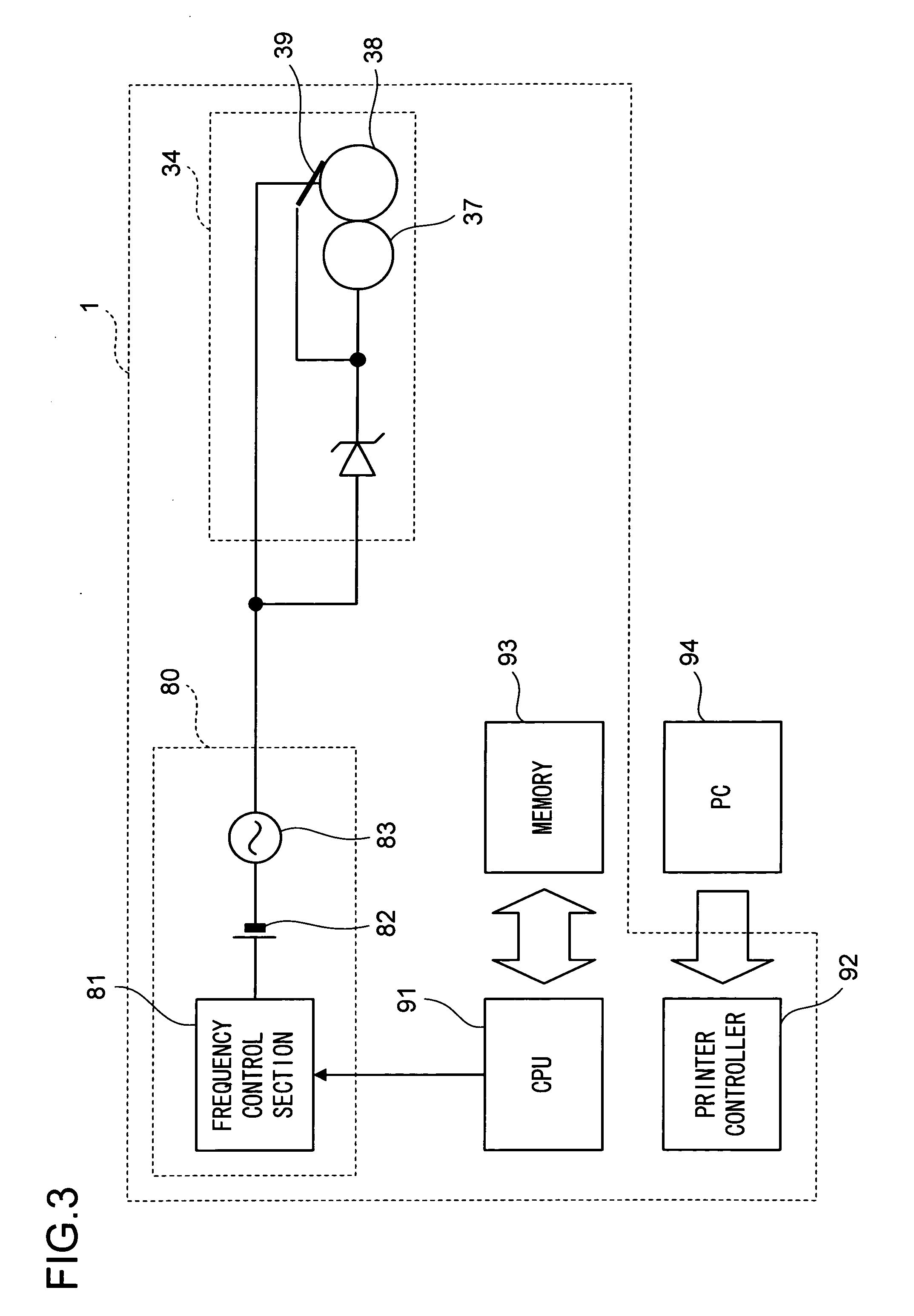
[0039]Description will be given below of an embodiment of the present invention with reference to the accompanied figures. FIG. 1 is a front view schematically showing the structure of an image forming apparatus of a first embodiment of the present invention. The image forming apparatus 1 is a printer that is connected to a personal computer 94 (see FIG. 3), and forms an image according to an instruction given by the personal computer 94.

[0040]At the bottom of the image forming apparatus 1, a paper feeding section 5 is provided. Above the paper feeding section 5, there is provided a transport section 4 having a rotating endless belt 42. The transport section 4 is connected to the paper feeding section 5 via a first transport passage 2, and transports recording paper fed from the paper feeding section 5.

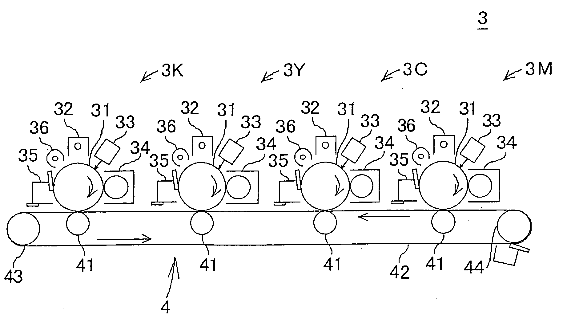
[0041]Above the transport section 4, an image forming section 3 is provided. The image forming section 3 is provided with image forming units 3M, 3C, 3Y, and 3K that correspond to fou...


PUM


Abstract

In an image forming apparatus 1 including a photoconductive drum 31 on which an electrostatic latent image is formed and a developer carrier that is allowed to carry a developer thereon by a developing bias voltage applied thereto composed of a DC component and an AC component and that is arranged in the vicinity of the photoconductive drum 31, the image forming apparatus 1 visualizing the electrostatic latent image using the developer carried on the developer carrier, a high-frequency region A with respect to which image forming is performed with the frequency of the AC component of the developing bias voltage increased and a low-frequency region B with respect to which image forming is performed with the frequency of the AC component of the developing bias voltage decreased are formed in an image to be formed on recording paper.

Description

[0001]This application is based on Japanese Patent Application No. 2007-072328 filed on Mar. 20, 2007, the contents of which are hereby incorporated by reference.BACKGROUND OF THE INVENTION[0002]1. Field of the Invention[0003]The present invention relates to an image forming apparatus in which an electrostatic latent image is visualized with a developer carried on a developer carrier.[0004]2. Description of Related Art[0005]A conventional image forming apparatus is disclosed in JP-A-H11-272048. This image forming apparatus has a photoconductive drum on which an electrostatic latent image is formed based on image data. A developing device having a developer carrier carrying a developer thereon is arranged so as to face the photoconductive drum. The developer is so-called mono-component nonmagnetic toner, which contains no magnetic carrier. A developing bias voltage composed of a DC component and an AC component is applied to the developer carrier, and this allows the developer carrie...

Claims


Application Information

Patent Timeline
Patent Type & Authority Applications(United States)
IPC IPC(8): G03G15/08
CPCG03G2215/0614G03G15/065
Inventor SAIKI, KATSUSHI
Owner KYOCERA DOCUMENT SOLUTIONS INC
Why Eureka
Try Eureka