An electrospinning nanofiber generating device

A nanofiber and generating device technology, which is applied in fiber processing, textile and papermaking, filament/wire forming, etc., can solve problems such as uneven electric field distribution, uneven nanofiber products, discharge at both ends, etc., to improve uniformity and production efficiency, the effect of suppressing the concentration change of the spinning solution and improving the stability

Active Publication Date: 2019-10-01
上海云同新材料科技有限公司
View PDF18 Cites 0 Cited by
  • Summary
  • Abstract
  • Description
  • Claims
  • Application Information

AI Technical Summary

Problems solved by technology

[0008] The above-mentioned slit electrospinning device has uneven electric field distribution along the slit direction, and the electric field intensity at both ends is much higher than that in the middle, which will cause uneven spinning jet distribution during the spinning process, and then the collected Nanofiber product uneven
Moreover, using too long straight slits for electrospinning is prone to discharge at both ends or no filaments in the middle.

Method used


Image

  • An electrospinning nanofiber generating device
  • An electrospinning nanofiber generating device
  • An electrospinning nanofiber generating device

Examples


Embodiment 1

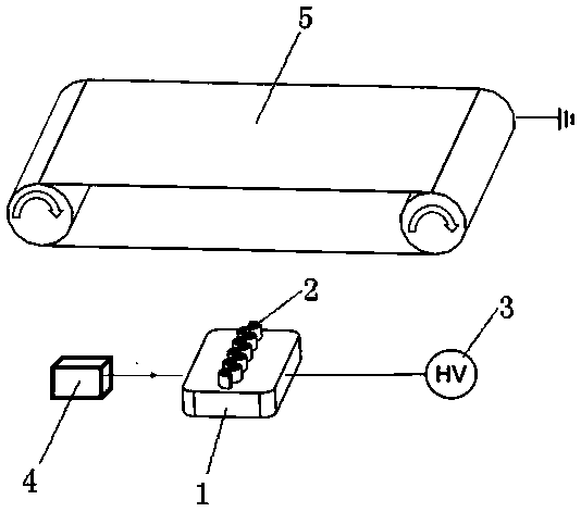
[0058] Such as figure 1 As shown, the fiber collecting device 5 included in the present invention is driven to rotate by a driving device, for example, a motor drives the fiber collecting device 5 to rotate at a speed of 40 rpm. The fiber collection device 5 is connected to the ground electrode of the high voltage generator 3 for receiving the generated nanofibers. The distance between the curved slit of the spinneret 2 and the fiber collection device 5 is 200 mm.

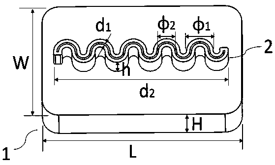
[0059] figure 2 shown as figure 1 A more detailed view of the middle spinneret. The specific shape of the curved slit is arc-shaped, the width d1 of the slit is 2 mm, the diameter ϕ2 of the inner circle where each spinneret slot 2 is located is 8 mm, the diameter ϕ1 of the outer circle is 12 mm, and the diameter ϕ1 of the spinneret slot 2 is 12 mm. The effective length d2 of the slit along the X axis is 100 mm, and the distance h between the top of the slit and the spinning cavity 1 is 10 mm. The length L of ...

Embodiment 2

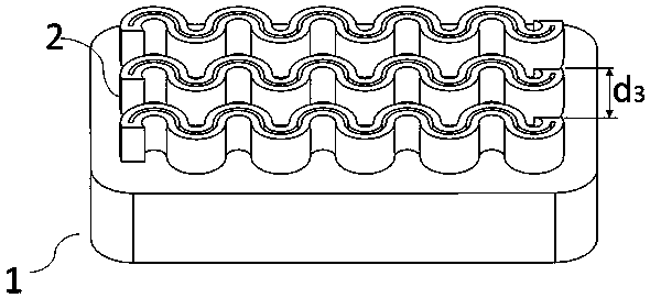
[0065] The spinneret line slot 2 reference that this embodiment uses image 3, the spinneret slot 2 shown in the figure is specifically a parallel arrangement of three curved slits, and the distance d3 between the slits of two adjacent spinneret slots 2 is 10 mm. The law of this parallel arrangement is that the crests of adjacent curved slits are opposite to the crests, and the troughs are opposite to the troughs. The parameters of each curved slit are the same as those in Example 1, and the parameters of the spinning cavity 1 are also the same as those in Example 1. The material of the spinning cavity 1 is polytetrafluoroethylene plastic, and the material of the curved slit is aluminum.

[0066] For experimental purposes, the nanofibers were formed using a polymer solution produced by Sigma-Aldrich with a viscosity of 1800 mPa s containing PVDF (polyvinylidene fluoride, average molecular weight 10,000). During spinning, the applied voltage was 70 kV. The feed rate of the P...

Embodiment 3

[0070] The spinneret line slot 2 reference that this embodiment uses Figure 11 , the spinneret groove 2 shown in the figure is specifically a broken line structure, and the half width d4 of the broken line slit is 10 mm, the inner width d5 ​​of a single repeating unit of the broken line slit is 6 mm, and the outer width d6 is 10 mm. The parameters of the spinning chamber 1 are the same as those in Example 1. The materials of the spinning cavity 1 and the curved slit are polypropylene plastics.

[0071] For experimental purposes, an aqueous polymer solution produced by Sigma-Aldrich with a viscosity of 1200 mPa s containing PVA (polyvinyl alcohol with an average molecular weight of 146,000 to 186,000 and 96% hydrolyzed) was used to form the nanofibers. The device shown in the figure can also use other polymer solutions to produce nanofibers. When spinning, the high voltage generator 3 charges the polymer solution so that a potential difference of 70 kV is generated between t...


PUM

PropertyMeasurementUnit
widthaaaaaaaaaa
lengthaaaaaaaaaa
heightaaaaaaaaaa

Abstract

The invention discloses an electrostatic spinning nanofiber generating device. The electrostatic spinning nanofiber generating device comprises a fiber generator, a fiber collecting device and a high-voltage generator, wherein the fiber generator comprises a spinning cavity, silk spray thread slots and a liquid storage tank; a slit is formed in each silk spray thread slot, and is communicated with the inner part of the spinning cavity; the liquid storage tank is communicated with the spinning cavity; each silk spray thread slot adopts a structure with twists and turns; the fiber collecting device is placed right above the silk spray thread slots; the high-voltage generator is provided with a high-voltage terminal and a ground terminal. According to the electrostatic spinning nanofiber generating device disclosed by the invention, nanofibers are produced by using viscous liquid as raw materials and utilizing an electrostatic spinning principle. Compared with the prior art, the core of the electrostatic spinning nanofiber generating device disclosed by the invention is the fiber generator with the bent slits; through the adoption of the fiber generator, the change of the concentration of spinning liquid, which is caused by solvent evaporation, is effectively inhibited, so that the producing stability of the nanofibers is greatly improved; besides, the uniformity and the production efficiency of produced fiber films are improved, so that the electrostatic spinning nanofiber generating device is suitable for the continuous scale production of nanofibers.

Description

technical field [0001] The invention relates to a fiber generating device, in particular to an electrospinning nanofiber generating device, which belongs to the technical field of electrospinning. Background technique [0002] The following description about the background technology of the present invention is for explaining the content of the present invention, but not to admit that all the materials mentioned have been published, known or part of the common knowledge on the priority date of the application. [0003] Nanofibers generally refer to ultrafine fibers with a diameter of less than 1000 nm. Compared with ordinary fibers, nanofibers have the advantages of large specific surface area and high porosity, and have broad application prospects in many fields. Electrospinning technology is a commonly used technology for preparing nanofibers, which has a wide range of applications, simple operation and controllable process. The basic principle of electrospinning technol...

Claims


Application Information

Patent Timeline
Patent Type & Authority Patents(China)
IPC IPC(8): D01D5/00
CPCD01D5/0069D01D5/0076D01D5/0092
Inventor 林童牛海涛颜贵龙
Owner 上海云同新材料科技有限公司
Why Eureka
Try Eureka