
Anchoring Element, Dental Anchoring Member, and Dental Anchorning Unit

Inactive Publication Date: 2008-09-25
BRANEMARK INTEGRATION
View PDF23 Cites 7 Cited by
  • Summary
  • Abstract
  • Description
  • Claims
  • Application Information

AI Technical Summary

Benefits of technology

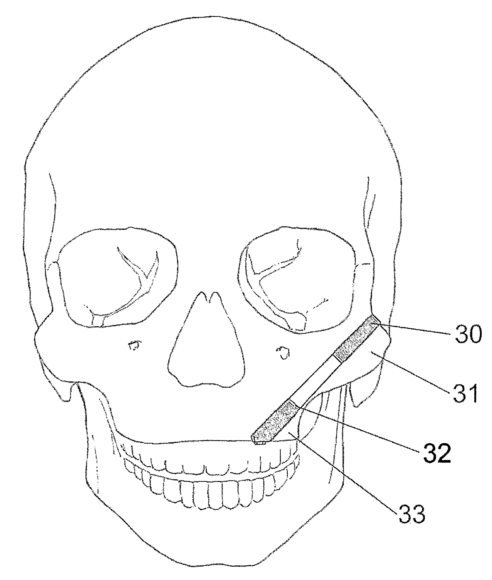
[0006]The object of the present invention is therefore to provide an anchoring element, a dental anchoring member, and a dental anchoring unit which effectively are anchored in bone tissue, and join various separated bone tissues at various locations in the body with a low risk of inflammations and other complications. Further, the object of the present invention is to provide an anchoring element and a dental anchoring member which improve and facilitate the fixation in the maxilla when a fixation shall be made in both the maxilla and the os zygomaticum, especially on patients with poor bone quality. The object of the present invention is also to provide an anchoring element, a dental anchoring member, and a dental anchoring unit which improve the fixation in the os zygomaticum. A further object of the present invention is to provide a dental anchoring unit enabling the fixation of a denture or a dental bridge in the upper region of the maxillary sinus on patients without a maxilla.SUMMARY OF THE INVENTION

Problems solved by technology

This is problematic since the maxilla of patients with poor bone quality is often very thin.
If there is a poor fixation in the maxilla, there is a major risk of inflammations and other complications.
Prior fixation elements do not completely succeed in solving this problem.
Further, the fixation in the os zygomaticum of prior fixation elements is not strong enough.

Method used


Image

  • Anchoring Element, Dental Anchoring Member, and Dental Anchorning Unit
  • Anchoring Element, Dental Anchoring Member, and Dental Anchorning Unit
  • Anchoring Element, Dental Anchoring Member, and Dental Anchorning Unit

Examples


Embodiment Construction

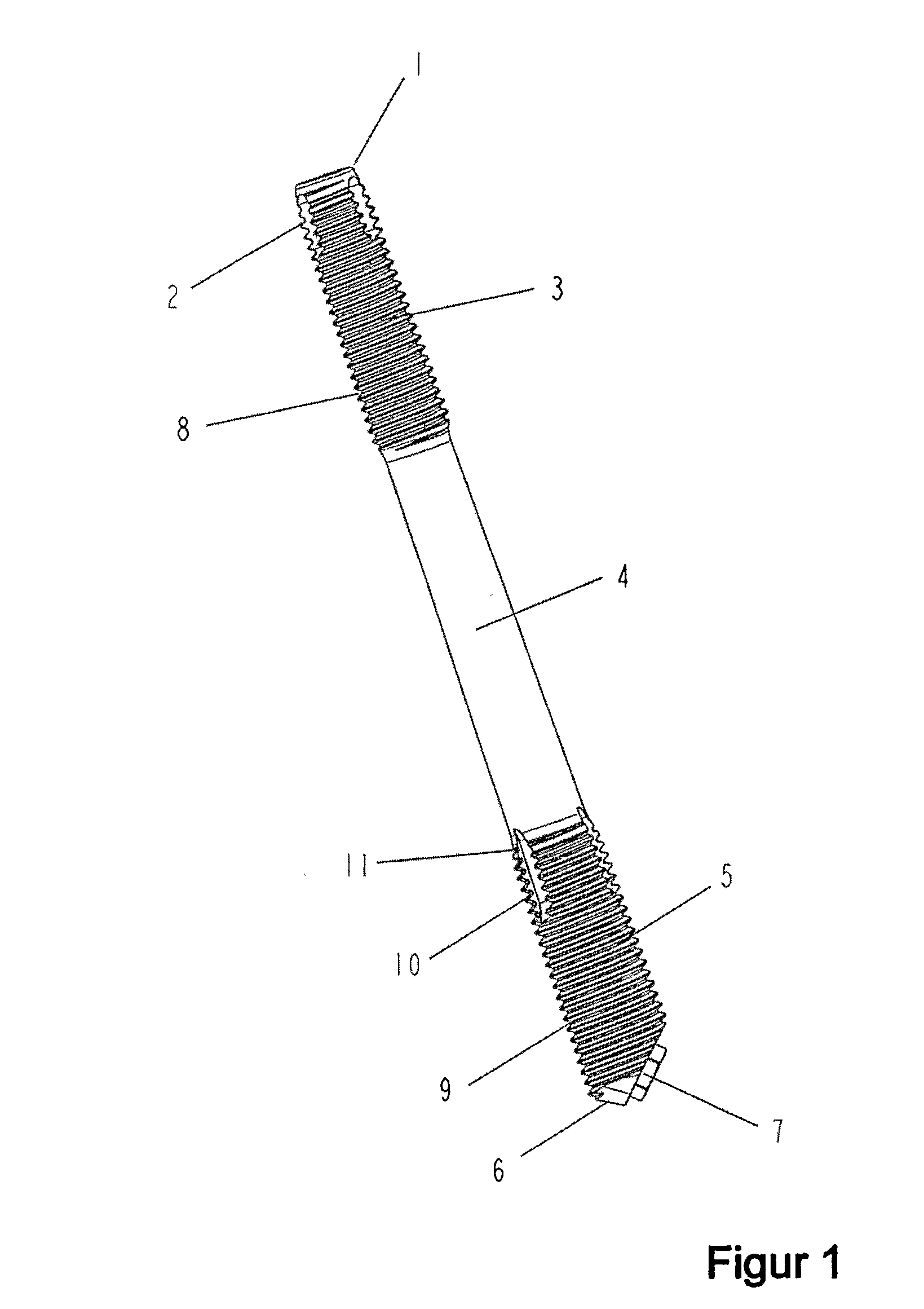
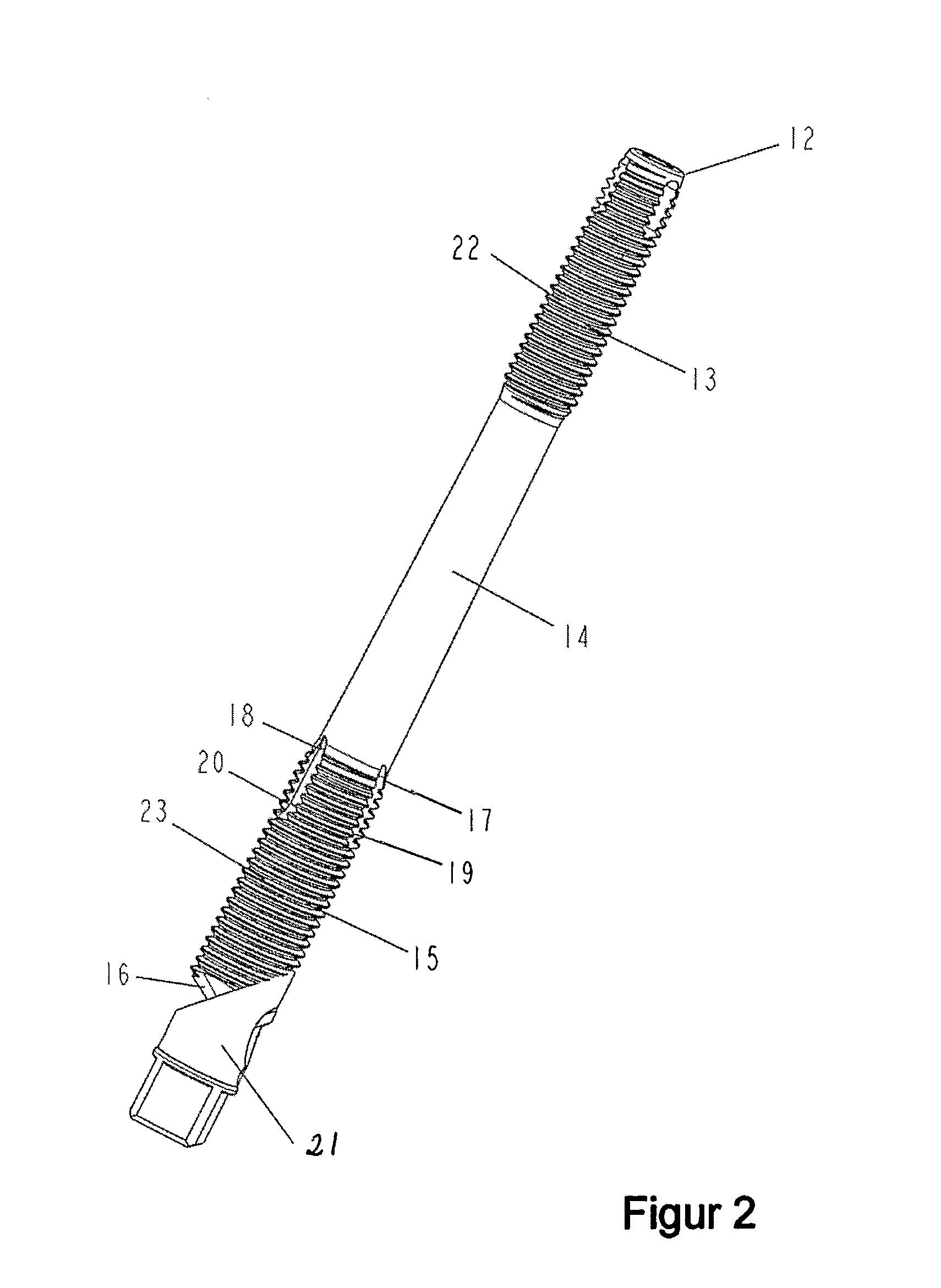
[0023]FIG. 1 shows an embodiment of the anchoring element according to the invention, for fixation in a first bone tissue and in a second bone tissue, the first and second bone tissues being separated by non-bone tissue. The anchoring element comprises an apex 1 according to prior art, provided with elongated recesses 2 which function as cutting units when the apex 1 is screwed into the first bone tissue and thus form grooves in which the threads engage. Adjacent to the apex 1 there is a threaded first fixation portion 3 which together with the apex 1 is adapted for fixation in the first bone tissue, and has the form of a truncated cone having the smaller basis adjacent to the apex 1 and the larger basis adjacent to an intermediate portion 4. Adjacent to the intermediate portion 4 there is a second fixation portion 5 adapted for fixation in the second bone tissue, and has the form a truncated cone having the smaller basis adjacent to the intermediate portion 4 and the larger basis f...


PUM


Abstract

An anchoring element and an dental anchoring member for fixation in a first bone tissue and in a second bone tissue, each comprising an apex (1, 12) and 5 a first fixation portion (3, 13) disposed at the apex (1, 12), both adapted for fixation in the first bone tissue, a basis (6, 16), and a second fixation portion (5, 15) disposed at said basis (6, 16) and adapted for fixation in the second bone tissue, and an intermediate portion (4, 14). The second fixation portion (5) of the anchoring element has the form of a truncated cone while the second fixation portion (15) of to the dental anchoring member is threaded and comprises at least one groove forming cutting unit transverse to the threads and disposed at the intermediate portion (14). A dental anchoring unit for fixation in the os zygomaticum, the dental anchoring unit being elongated and comprising an apex (24) and a fixation portion (25) disposed at the apex (24), both adapted for fixation in the os zygomaticum, a basis (26), and an end portion (27) disposed between the fixation portion (25) and said basis (26). The fixation portion (25) has the form of a truncated cone having the smaller basis adjacent to the apex (24) and the larger basis adjacent to the end portion (27).

Description

TECHNICAL FIELD[0001]The present invention relates to an elongated anchoring element and an elongated dental anchoring member for fixation in a first bone tissue and in a second bone tissue, the first and second bone tissues being separated by non-bone tissue, comprising an apex and a first fixation portion disposed at the apex, both adapted for fixation in the first bone tissue, a basis, and a second fixation portion disposed at said basis and adapted for fixation in the second bone tissue, and an intermediate portion positionable in the non-bone tissue separating the first and second bone tissues. Further, the invention relates to a dental anchoring unit for fixation in a bone tissue, the dental anchoring unit being elongated and comprising an apex and a fixation portion disposed at the apex, both adapted for fixation in the bone tissue, a basis, and an end portion disposed at said basis.BACKGROUND OF THE INVENTION[0002]Upon treatment of patients with different bone fractures, the...

Claims


Application Information

Patent Timeline
IPC IPC(8): A61B17/04A61B17/56A61BA61B17/86A61C8/00
CPCA61C8/0034A61B17/863
Inventor OHRNELL, LARS-OLOFBRANEMARK, RICKARDMORENIUS, CARLNILSSON, PETERSVENSSON, THOMAS
Owner BRANEMARK INTEGRATION
Learn More