
Safety gate system having an electronic display

Inactive Publication Date: 2008-10-02
DAKTRONICS
View PDF28 Cites 18 Cited by
  • Summary
  • Abstract
  • Description
  • Claims
  • Application Information

AI Technical Summary

Benefits of technology

[0014]Yet another significant aspect and feature of this invention is the safety provided to fans in an enclosed setting by providing necessary egress points from the stadium onto the pitch.
[0015]One more significant aspect and feature is the concealed cabling to prevent tripping hazards.
[0016]Still a further significant aspect and feature is the fully enclosed mechanism and eased or beveled edges to eliminate clothing catches or snags.
[0020]Finally another significant aspect and feature of this invention is providing a low cost emergency exit system for sports fields.

Problems solved by technology

At musical concerts, barriers may keep attendees from physically interrupting a performance on stage.
However, traditional gates typically require attendants or officials to release each gate.
The first solution is undesirable because the accepting pit is expensive and a large capital investment is required.
Further, significant safety concerns accompany each lowering of a barrier while a crowd is in intimate contact with the moving barrier.
A hinge-to-horizontal barrier also is costly and is prone to safety concerns if tipped while in contact with a crowd.
The traditional gate solution, while initially less costly, remains highly labor intensive and still undesirable from a safety stand point because each gate relies upon the cool-headedness of each live attendant performing a task in a potentially life threatening crowd incursion situation.

Method used


Image

  • Safety gate system having an electronic display
  • Safety gate system having an electronic display
  • Safety gate system having an electronic display

Examples


Embodiment Construction

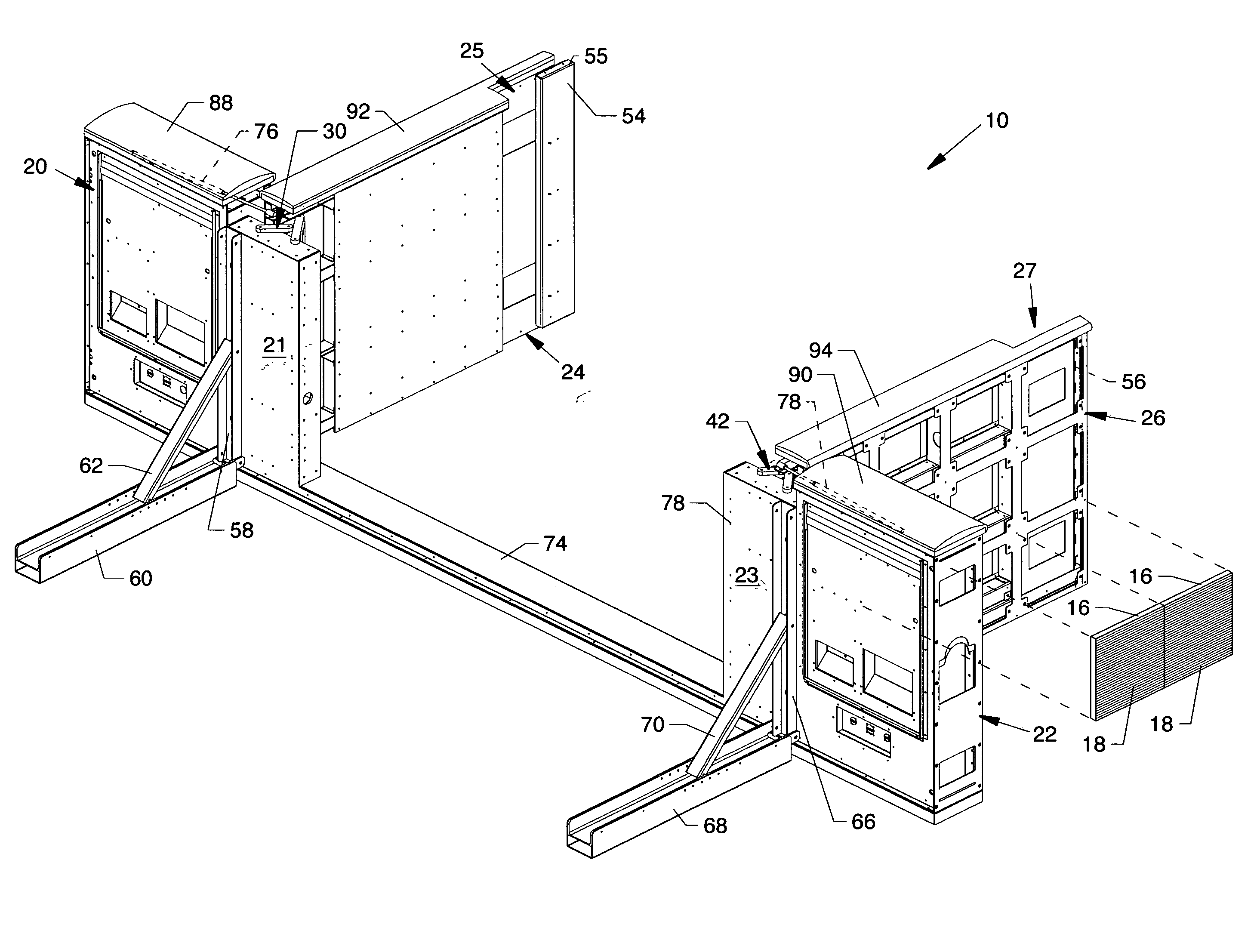
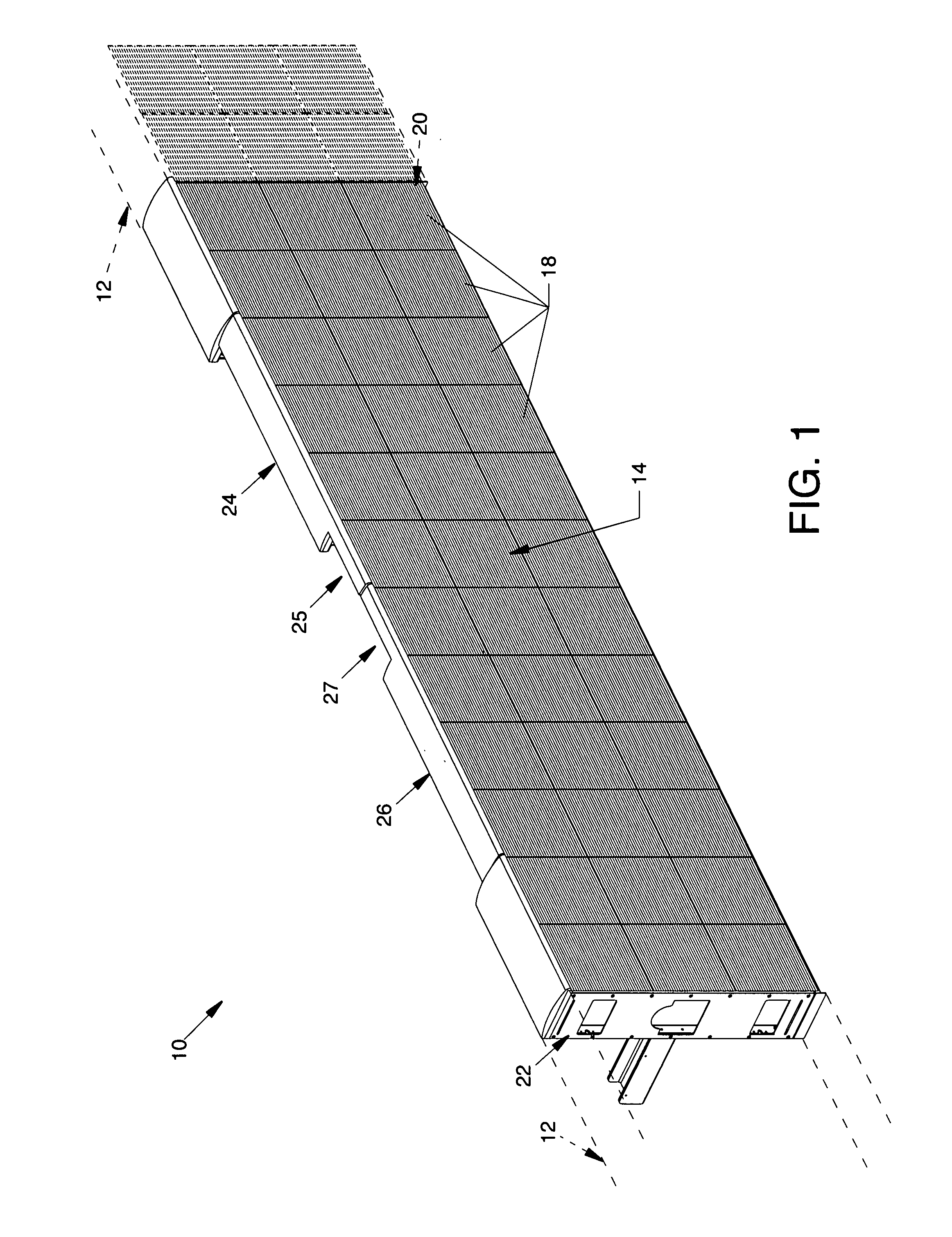
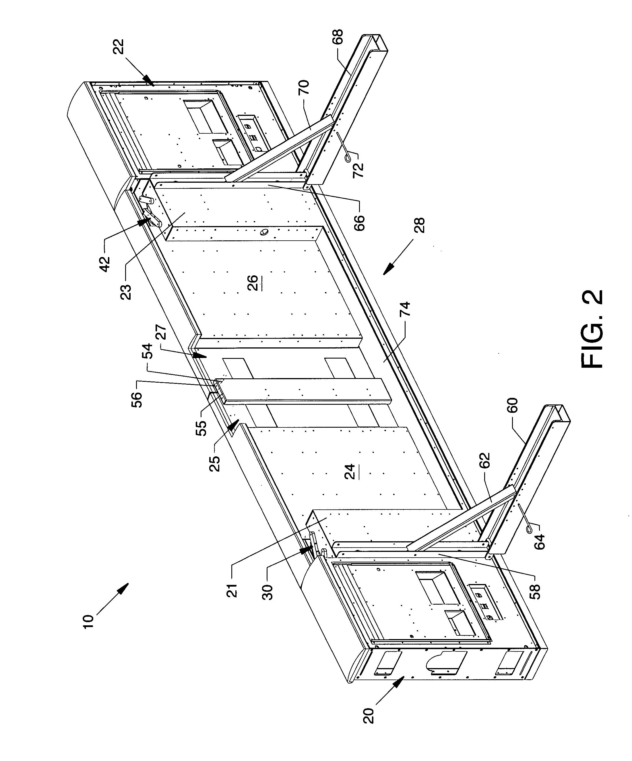
[0032]FIG. 1 is an isometric view of a safety gate system 10 of the present invention, shown aligned within and filling a gap in a barrier 12 (shown in ghost) or, alternatively, replacing a length or segment of barrier 12. As such, the safety gate system 10 may be considered a safety barrier or part of a safety barrier. It should be understood that the safety gate system 10 of the present invention also can be used in plural aligned arrangements of end-to-end safety gates 10, thereby forming a safety barrier. Preferably, safety gate systems 10 of the present invention can be situated at desirable locations along the barrier 12, such that the safety gate systems 10 may yield and thereby open at a preselected force pushing against the gates. Alternatively, the safety gate system 10 may be remotely opened. Opening of the safety gate system 10 reduces the pressure of a crowd of fans, thereby crushing injuries typically experienced by fans in dangerous crowds may be reduced or avoided. T...


PUM


Abstract

A safety gate system having an electronic display for seamless integration into a barrier with electronic display capabilities. The safety gate system includes a post and a gate hinged to the post. The gate face and post carry electronic display modules which appear when the gate is closed, as continuous with and seamlessly integrated into the display of the barrier. Preferably, the hinges are four-bar hinges, most preferably two sets of paired four-bar hinges. The safety gate also includes a lower chase or sill which allows both signal wiring and power to pass under the gate. Braced rear legs compensate for the cantilever forces of the gates when open. A latch, preferably an electromagnetic latch, auto-releases in response to a pre-set sufficient force level, such as arising crowd surge forces, being applied to the gate, as well as being remotely releasable.

Description

CROSS REFERENCES TO RELATED APPLICATIONS[0001]None.BACKGROUND OF THE INVENTION[0002]1. Field of the Invention[0003]The present invention is for controlling passage or access while providing an electronic display, and more particularly, pertains to a gate having electronic display capabilities and a variably controllable latch.[0004]2. Description of the Prior Art[0005]Barriers are typically employed for limiting passage or access of attendees at sports events and / or mass audience entertainment events. At musical concerts, barriers may keep attendees from physically interrupting a performance on stage. Barriers, such as those often situated about a soccer pitch periphery, serve to keep fans from interfering with athletes during an athletic match and may serve to limit fans to predetermined safe viewing locations. At the termination of an event, it may be desirable to enable passage through the barrier to facilitate fan dispersal. Additionally, in the event of a panic or stampede of a...

Claims


Application Information

Patent Timeline
IPC IPC(8): E06B11/02E06B7/00
CPCA63B71/06A63B2207/02A63B2243/0025E06B11/02Y10T16/5476G09F13/22G09F9/3026Y10T16/5475G09F9/33A63B2225/74
Inventor DEBLONK, JAY C.MILLER, KENT SHANECRIDDLE, DOUGLAS JOHN
Owner DAKTRONICS
Learn More