Pressure tube for a position measuring system

a technology of pressure tube and position measuring system, which is applied in the direction of instruments, operating means/releasing devices of valves, other domestic objects, etc., can solve the problems of laborious and expensive production of pressure tube according to the state of the art, and achieve the effect of cost-effective manufacturing

Inactive Publication Date: 2008-10-02
ROBERT BOSCH GMBH
View PDF6 Cites 2 Cited by
  • Summary
  • Abstract
  • Description
  • Claims
  • Application Information

AI Technical Summary

Benefits of technology

[0019]It is advantageous for the pressure tube to be made of non-magnetic steel since this makes it possible to implement a mechanically firm position measuring system and the influence exerted by the pressure tube on the measuring system is low.
[0020]Moreover, a pressure tube is provided for a position measuring system in which the pressure tube is made by deep-drawing. Such a pressure tube can be manufactured cost-effectively.

Problems solved by technology

The production of pressure a tube according to the state of the art is laborious and expensive.

Method used


Image

  • Pressure tube for a position measuring system
  • Pressure tube for a position measuring system
  • Pressure tube for a position measuring system

Examples


first embodiment

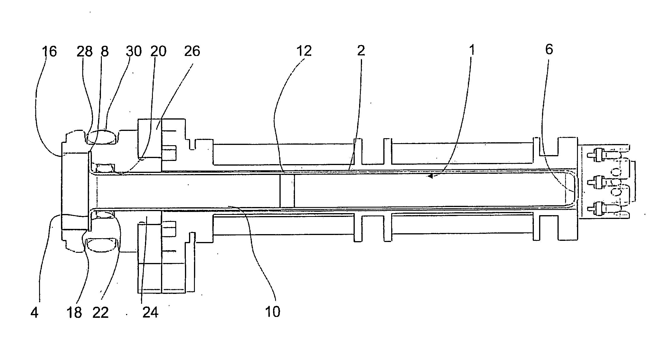
[0035]As an alternative to the first embodiment described above, the attachment flange 26 can be dispensed with if the attachment piece 14 is provided with a thread that can be screwed into the valve housing.

[0036]With the first embodiment and its variant, a cost-effective manufacturing process can be used for the pressure tube, even for pressures in the order of magnitude of several 100 bar, a process in which inexpensive O-rings are used to create a seal.

second embodiment

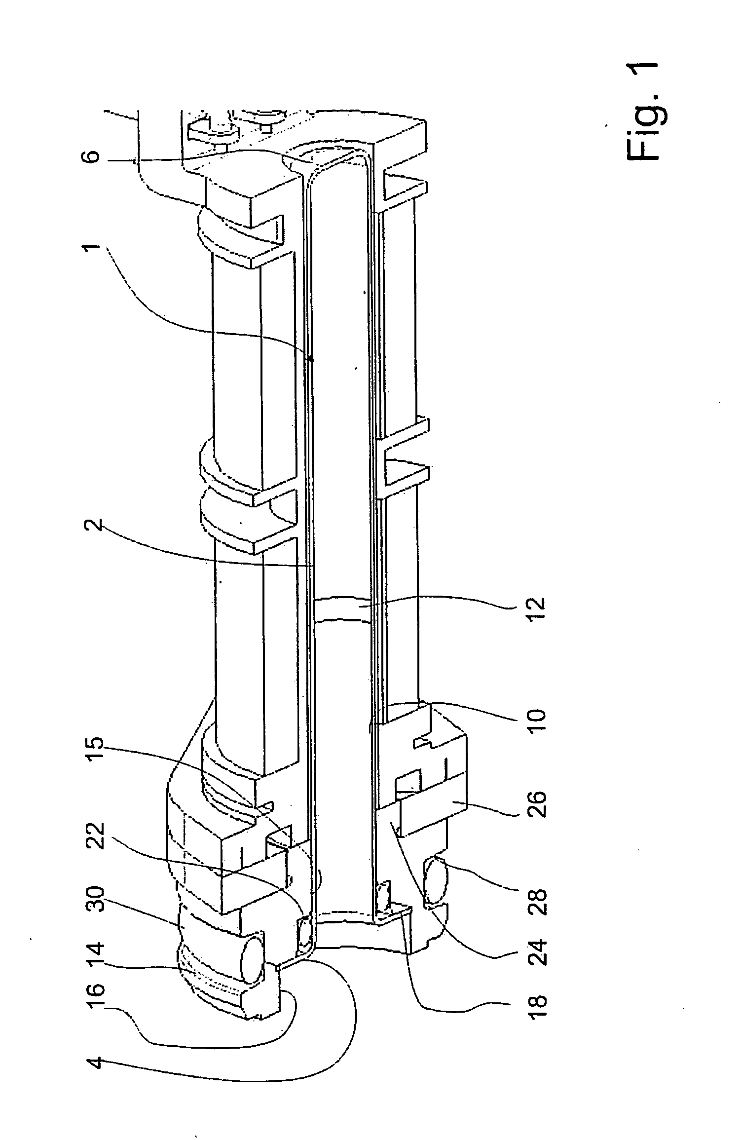
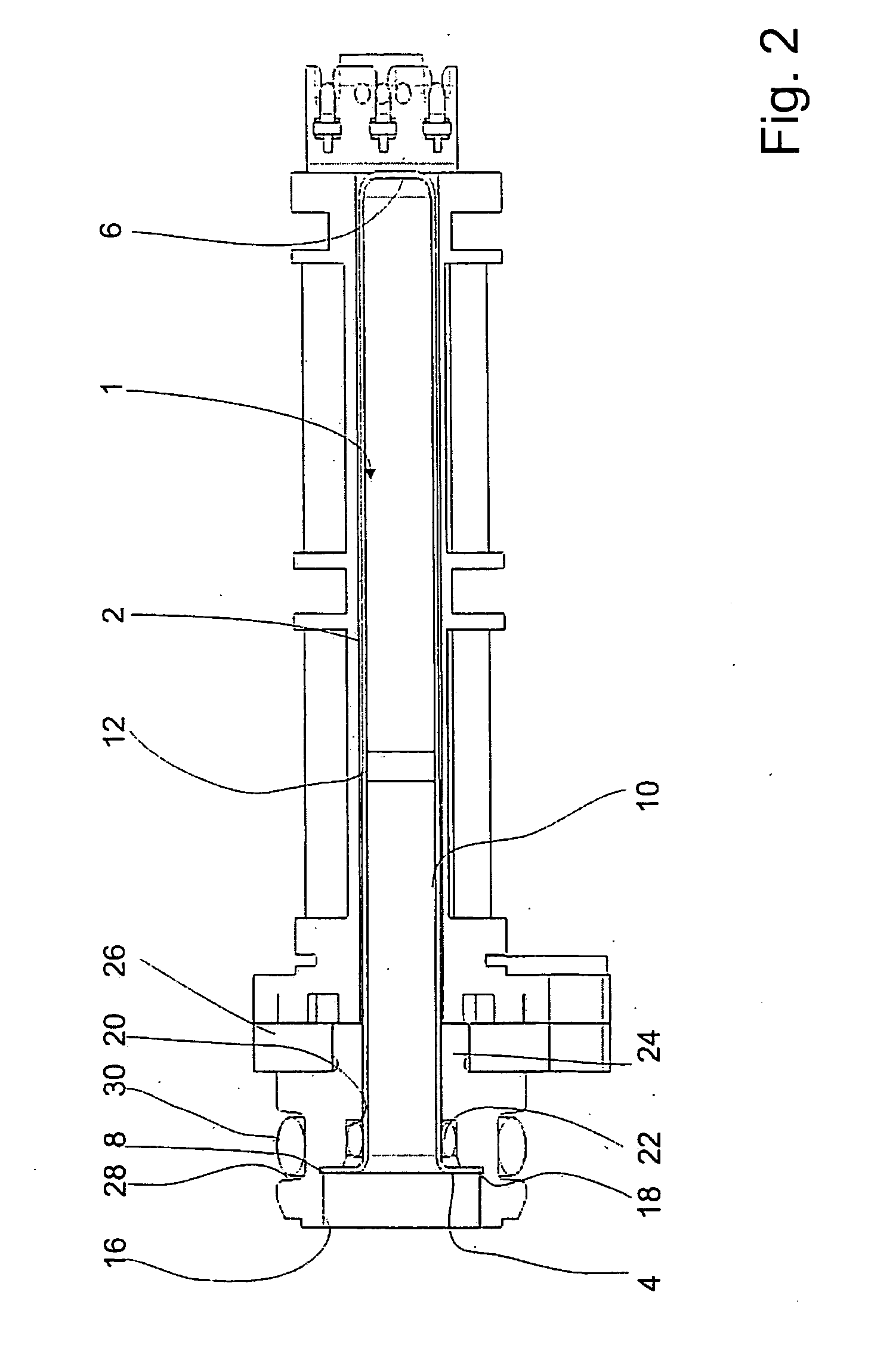
[0037]FIG. 3 shows a pressure tube 101 corresponding to the second embodiment and FIG. 4 depicts the pressure tube with a holding element and a sealing ring.

[0038]The pressure tube 101 of the second embodiment, like the pressure tube 1 of the first embodiment, has a face section 106 and a tube section 102. The tube section 102 of the second embodiment has a constant diameter along its entire length in the axial direction, as a result of which it does not exhibit any conical widening. The flange section 103 is configured symmetrically with respect to an axis X that runs through the mid-axis of the tube section 102 and it has two attachment cutouts 108a, 108b.

[0039]As an alternative to this, a conical widening corresponding to that of the first embodiment can be configured in the tube section 102. This conical widening then serves only to facilitate the manufacturing process employing the deep-drawing method.

[0040]As shown in FIG. 4, an essentially annular holding element 114 can be ...


PUM

PropertyMeasurementUnit
pressuresaaaaaaaaaa
pressureaaaaaaaaaa
circumferenceaaaaaaaaaa

Abstract

A position measuring system, especially for hydraulic valve, having a pressure tube to accommodate an armature is provided, whereby the pressure tube is manufactured by deep-drawing. As a result, a cost-effective manufacturing process can be employed for the pressure tube. The pressure tube can be firmly attached to a valve housing by means of a holding element and, optionally, an attachment flange.

Description

[0001]Priority is claimed to German Patent Application No. DE 10 2007 014 559.6, filed on Mar. 27, 2007, the entire disclosure of which is incorporated by reference herein.[0002]The present invention relates to pressure tube for a position measuring system, especially for a hydraulic valve.BACKGROUND[0003]German document DE 197 07 587 B4 discloses an electromagnetic control element with a pole tube which contains an armature that can be actuated by means of a solenoid coil, and comprising a pressure tube into which a ferrite core has been inserted. The position of the ferrite core relative to the pressure tube can be picked up by means of measuring coils provided along the outer circumference of the pressure tube. The pressure tube has a thickened flange that is joined to a magnetically conductive part of the pole tube by rolling it at an attachment site. In the state of the art, such pressure tubes are often manufactured by lathing a blank.[0004]As an alternative to manufacturing t...

Claims


Application Information

Patent Timeline
Patent Type & Authority Applications(United States)
IPC IPC(8): G01M19/00B21D51/18G01M99/00
CPCF16K31/0675Y10T29/494F16K37/0041
Inventor THIERBACH, PETERSTEPRATH, WERNER
Owner ROBERT BOSCH GMBH
Why Eureka
Try Eureka