Fuel shut-off valve

Active Publication Date: 2008-10-02
TOYODA GOSEI CO LTD
View PDF14 Cites 9 Cited by
  • Summary
  • Abstract
  • Description
  • Claims
  • Application Information

AI Technical Summary

Benefits of technology

[0032]In the seventh preferable modification of the fuel shut-off valve according to the first aspect of the present invention, the ring-shaped seat member further comprises a connecting portion, which is disposed between the base and the lip-shaped portion; and the ring-shaped groove is disposed between the connecting portion and the base, thereby neighboring the thin-film-shaped portion on the ring-shaped groove. As a result, the thin-film-shaped portion turns into a part that has a thinner thickness than that of the connecting portion, and that is more likely to deform than the connecting portion is. Accordingly, the thin-film-shaped portion flexes upon the float's seating on the lip-shaped portion of the ring-shaped seat member. Therefore, it is possible to secure the sealability between the float

Problems solved by technology

However, if such is the case, the lip-shaped portion exhibits weakened strength.
Consequently, the lip-shaped portion has exhibited degraded durability.
Therefore, there might arise such a fear that the seat member has come off from the upper valve element's valve body

Method used


Image

  • Fuel shut-off valve
  • Fuel shut-off valve
  • Fuel shut-off valve

Examples


example no.1

Example No. 1

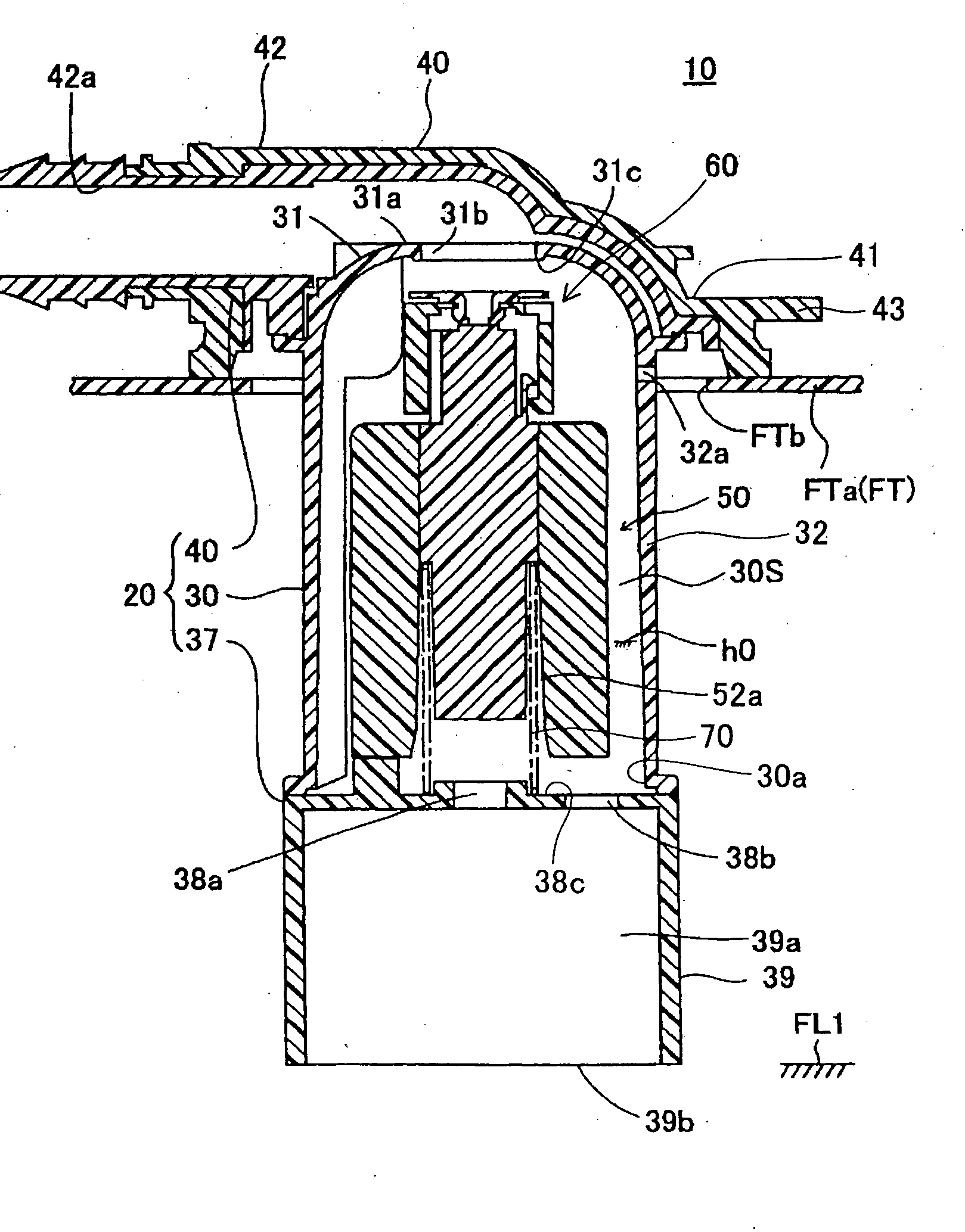
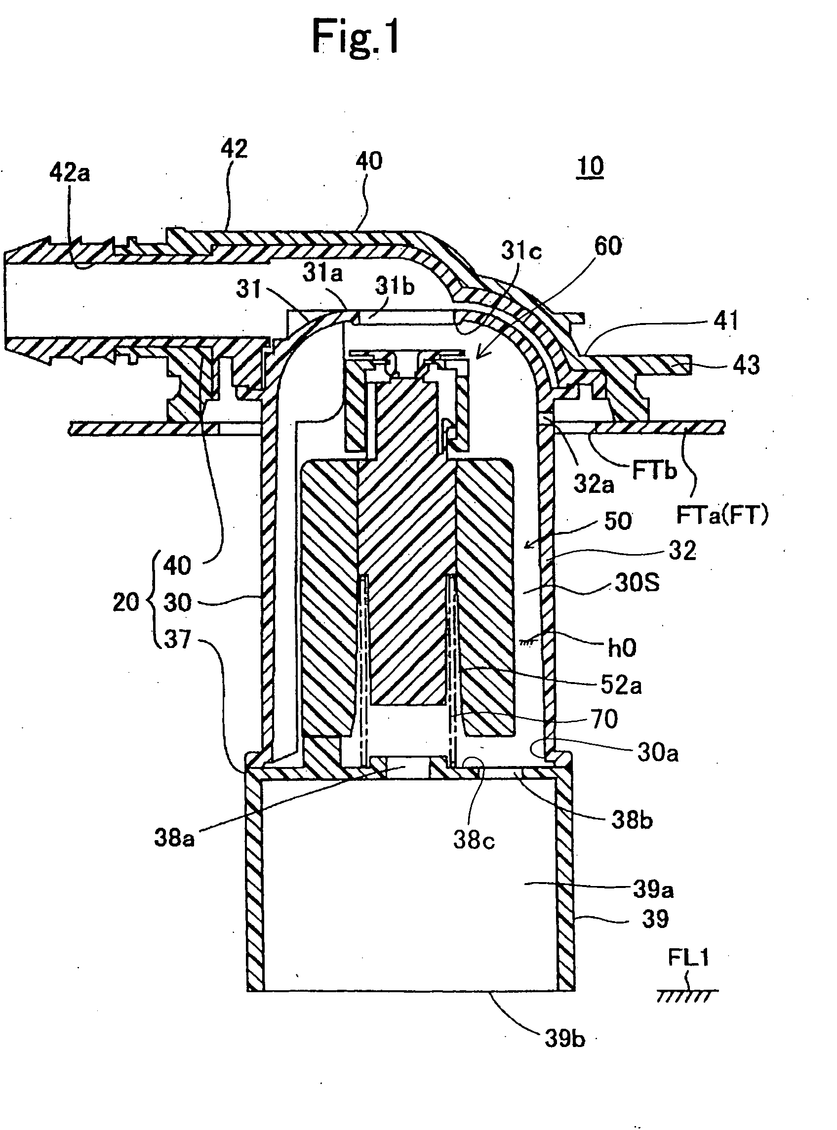
[0055]A fuel shut-off valve according to Example No. 1 of the present invention will be hereinafter described with reference to the drawings. As illustrated in FIG. 1, the present fuel shut-off valve 10 according to Example No. 1 is installed on the top of a fuel tank FT. The fuel tank FT has a surface that is formed of a composite resinous material containing polyethylene, and has a tank upper wall FTa that is provided with an installation hole FTb. The present fuel shut-off valve 10 is fixed on the tank upper wall FTa in such a manner that its bottom goes into the installation hole FTb. The present fuel shut-off valve 10 controls the flow of fuel into a canister when the fuel within the fuel tank FT ascends to a predetermined liquid level FL1 during fuel supply.

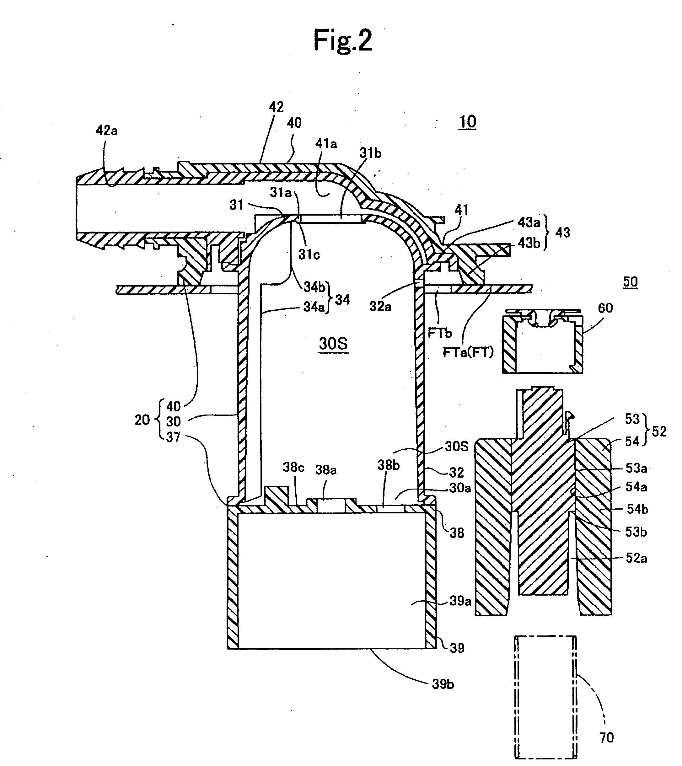
[0056]The present fuel shut-off valve 10 according to Example No. 1 comprises a casing 20, a float mechanism 50, and a spring 70, as the major component parts. The casing 20 comprises a casing body 30, a bottom...

example no.2

Example No. 2

[0078]A fuel shut-off valve according to Example No. 2 of the present invention will be hereinafter described with reference to FIG. 9. As illustrated in the drawing, the present fuel shut-off valve according to Example No. 2 differs from Example No. 1 in that the ring-shaped seat member 61 is fixed to the casing 20. Similarly to Example No. 1, the casing 20 comprises the casing body 30, which is surrounded by the top-walled portion 31 and side-walled portion 32. The central part of the casing body 30's top-walled portion 31 is provided with the passage-forming protrusion 31a. The passage-forming protrusion 31a protrudes radially inward, thereby facing to each other so as to make the connector passage 31b provisionally. The ring-shaped seat member 61, which is made from elastomer, is fixed to the passage-forming protrusion 31a. Moreover, the valve chamber 30S, which is surrounded by the casing 20, accommodates the float 52 therein. The float 52 ascends and descends by i...

example no.3

Example No. 3

[0083]A fuel shut-off valve according to Example No. 3 of the present invention comprises a modified version of the ring-shaped seat member 61. Specifically, as illustrated in FIG. 10, this ring-shaped seat member 61 comprises the base 61a, and the thin-film-shaped portion 61g. Contrary to the ring-shaped seat member 61 of Example Nos. 1 and 2, this ring-shaped seat member 61 comprises the thin-film-shaped portion 61g, which extends horizontally from the base 61a in a diametrically inward direction of the ring-shaped seat member 61. Moreover, this ring-shaped seat member 61 is free from the ring-shaped groove 61h that is disposed between the base 61a and the lip-shaped portion 61e in the ring-shaped seat member 61 of Example Nos. 1 and 2. In addition, this ring-shaped seat member 61 comprises the lip-shaped portion 61e, which is disposed at the diametrically-inward leading end of the thin-film-shaped portion 61g. Note that the lip-shaped portion 61e has a thickness T2, ...


PUM


Abstract

A fuel shut-off valve includes a casing, an ascendable and descendible float, and an upper valve element, which is actuated by the float to open and close connector passage that communicates the inside of fuel tank with the outside, and which includes a valve body and a ring-shaped seat member. The ring-shaped seat member makes a connector bore, which communicates with the connector passage, therein, and includes a base, a holding portion, a seating portion, a lip-shaped portion, and a thin-film-shaped portion. The seating portion opens and closes the connector passage, and defines an opening of the connector bore. The lip-shaped portion seats on and separates away from the float, and defines the other opening of the connector bore. The thin-film-shaped portion is disposed between the base and the lip-shaped portion, and is deformable elastically upon being pressed by the float when the float seats on the lip-shaped portion.

Description

[0001]The present invention is based on Japanese Patent Application No. 2007-95,186, filed on Mar. 30, 2007, and on Japanese Patent Application No. 2007-249,062, filed on Sep. 26, 2007, the entire contents of which are incorporated herein by reference.BACKGROUND OF THE INVENTION[0002]1. Field of the Invention[0003]The present invention relates to a fuel shut-off valve, which shuts off fuel from flowing out of discharge port for discharging gases that generate in the fuel tank of vehicle.[0004]2. Description of the Related Art[0005]Within a fuel tank, a fuel shut-off valve has been disposed usually. The fuel shut-off valve not only discharges gases that generate resulting from evaporating fuel, but also shuts off the fuel from flowing out of the discharge port. As one of such fuel shut-off valves, a conventional fuel shut-off valve has been know that comprises a casing, a float, and an upper valve element. The casing is installed on the top of fuel tank, and has a top being provided ...

Claims


Application Information

Patent Timeline
IPC IPC(8): F16K31/18
CPCF16K24/044F16K25/00Y10T137/053Y10T137/3099
Inventor HORIBA, SHOJINISHI, HIROSHIMORI, NAOKI
Owner TOYODA GOSEI CO LTD
Why Eureka
Try Eureka