
Time continuous pipeline analog-to-digital converter

a technology of analog-to-digital converter and time-continuous pipeline, which is applied in the direction of code conversion, transmission system, instruments, etc., can solve the problems of introducing quantitative errors of adc, affecting the quality of the pipeline, and so on, so as to reduce the noise of the next stage of the pipeline. , to achieve the effect of reducing high-frequency broadband

Active Publication Date: 2008-10-02
NATIONAL INSTRUMENTS
View PDF17 Cites 16 Cited by
  • Summary
  • Abstract
  • Description
  • Claims
  • Application Information

AI Technical Summary

Benefits of technology

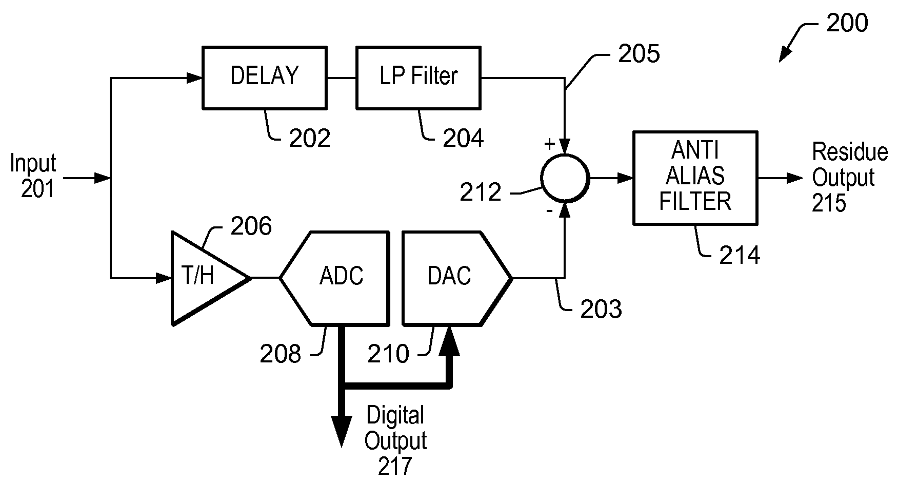
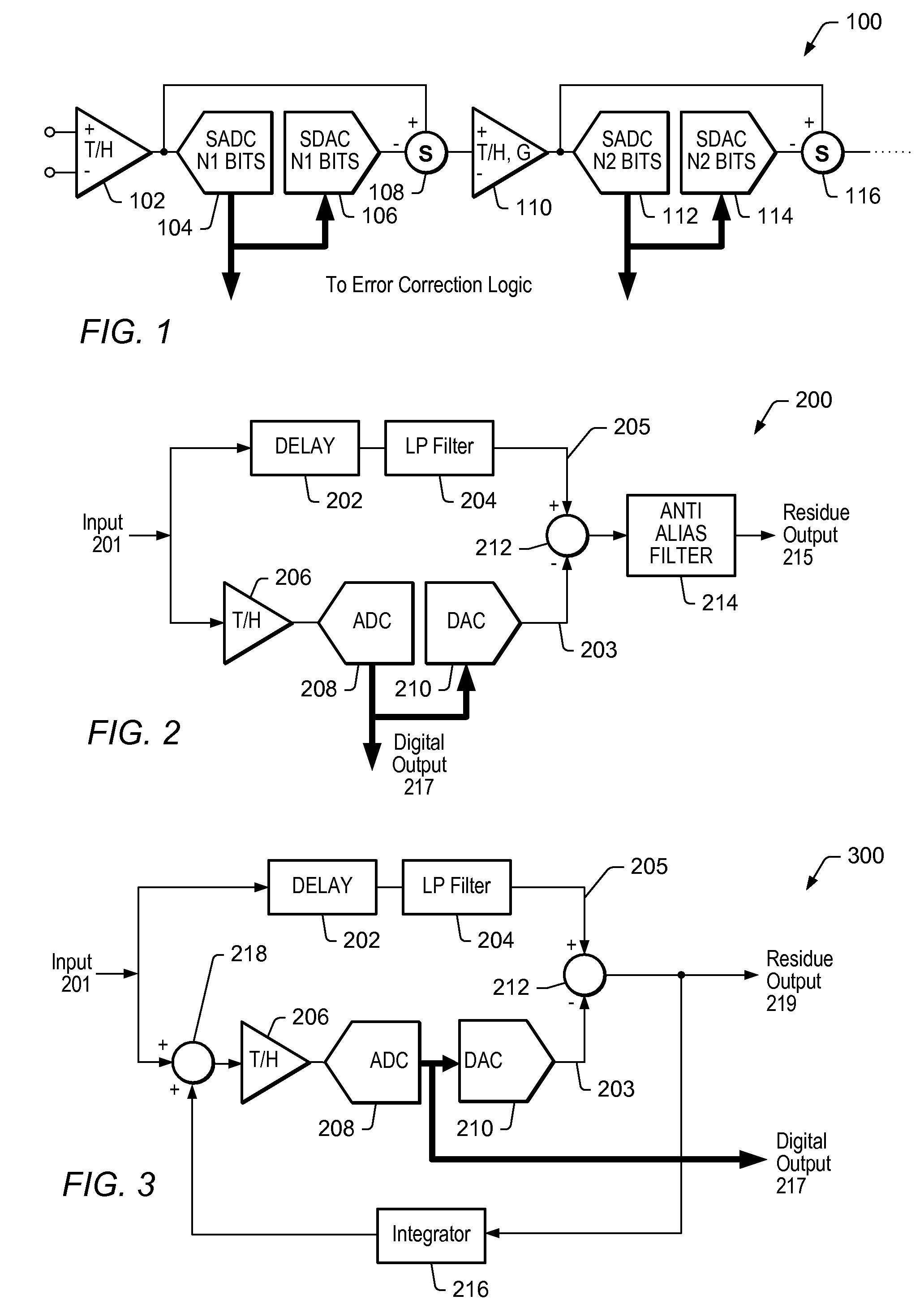
[0017]The delay block may be configured to delay the analog input signal in order for the output of the DAC and the output of the LP filter entering the difference block (before the anti alias filter) to be delayed equally. By minimizing the delay between the output of the DAC and the output of the LP filter, the amplitude of the difference between the output of the DAC and the output of the LP filter may effectively be minimized. In one set of embodiments, the delay block may be implemented as either a high order passive low pass filter or as a delay line in form of a cable, or a delay line on a printed circuit board (PCB). Those skilled in the art will appreciate that alternate embodiments may feature implementations of the delay element other than those mentioned herein.
[0019]The anti alias filter may be configured to remove high frequency noise components originating from the quantization performed by the ADC, as well as to remove high frequency mirrors of the input signal on the output of the DAC. In addition, bandwidth limitation introduced through the anti alias filter may result in the reduction of high frequency broadband noise that may be characteristic of the operation of the DAC.

Problems solved by technology

One difference between the analog input signal and the output signal generated by the DAC may result from quantization errors introduced by the ADC.
Differences (between the analog input signal and the output generated by the DAC) attributed in large part to the absence of a track and hold component—and different from differences resulting from quantization errors—may be considered undesirable, as they may result in a residue so large that the next stage in the pipeline might saturate.

Method used


Image

  • Time continuous pipeline analog-to-digital converter
  • Time continuous pipeline analog-to-digital converter
  • Time continuous pipeline analog-to-digital converter

Examples


Embodiment Construction

[0027]As used herein, “combining signals” includes but is not limited to adding the signals or portions of the signals together, subtracting the signals or portions of the signals from each other, or multiplying the signals or portions of the signals together, or performing any combination thereof.

[0028]FIG. 2 shows a single stage 200 of a time-continuous implementation (i.e. without a track and hold) of a Sampled Pipeline Subranging Converter (SPSC), equivalent to a single conversion stage in the SPSC. The analog input 201 may be processed in two parallel paths. A lower path may comprise a track-and-hold (T / H) element 206, an Analog-to-Digital-Converter (ADC) 208 and a Digital-to-Analog-Converter (DAC) 210. T / H 206 is optional and may be present if required by ADC 208. The lower path may be sampled at the desired conversion rate. As in the SPSC shown in FIG. 1, DAC 210 may output an analog representation of input signal 201. However, the output signal 203 of DAC 210 may differ from...


PUM


Abstract

A Sampled Pipeline Subranging Converter (SPSC) may include at least one stage—e.g. at least the input stage—operating in a time-continuous fashion. In the time continuous input stage, the analog input may be processed in two parallel paths. A lower path may comprise a track-and-hold (T / H) element, an Analog-to-Digital-Converter (ADC) and a Digital-to-Analog-Converter (DAC). The T / H element may be optional and may be present if required by the ADC. The signal entering the lower path may be sampled at the desired conversion rate. The time continuous stage(s) may additionally be configured with an upper path that includes a delay element configured to receive the analog input, a Low-Pass (LP) filter coupled to the delay element, and an anti alias filter. The output generated by the DAC may be subtracted from the output of the LP filter, and the resulting difference signal may be provided to the anti alias filter, which in turn may generate the residue (or error) output. The digital output of the time continuous converter may be calculated by combining the digital outputs of the various sections.

Description

BACKGROUND OF THE INVENTION[0001]1. Field of the Invention[0002]This invention relates generally to analog-to-digital converter (ADC) design and, more particularly, to the design of a time continuous pipeline ADC.[0003]2. Description of the Related Art[0004]Scientists and engineers often use measurement systems to perform a variety of functions, including measurement of a physical phenomena or unit under test (UUT), test and analysis of physical phenomena, process monitoring and control, control of mechanical or electrical machinery, data logging, laboratory research, and analytical chemistry, to name a few examples.[0005]A typical measurement system comprises a computer system, which commonly features a measurement device, or measurement hardware. The measurement device may be a computer-based instrument, a data acquisition device or board, a programmable logic device (PLD), an actuator, or other type of device for acquiring or generating data. The measurement device may be a card ...

Claims


Application Information

Patent Timeline
IPC IPC(8): H03M1/50
CPCH03M1/124H03M1/167
Inventor KNUDSEN, NIELS
Owner NATIONAL INSTRUMENTS
Learn More