
Self-adjusting clamp system

a self-adjusting, clamping technology, applied in the direction of supporting structure mounting, electrical apparatus construction details, instruments, etc., can solve the problems of increasing the cost (in terms of time, labor and expense) of manufacturing such components, and the possibility of failure, so as to avoid the stress

Active Publication Date: 2008-10-02
PARKER INTANGIBLES LLC
View PDF12 Cites 10 Cited by
  • Summary
  • Abstract
  • Description
  • Claims
  • Application Information

AI Technical Summary

Benefits of technology

[0006]The present invention provides a wedge lock clamping assembly, system and method that can accommodate tolerance variations and misalignments while avoiding the stresses caused by prior art wedge lock systems. In particular, the present invention provides a wedge lock clamping assembly, system and method that self-adjusts to compensate for any misalignment between the module and guide slot in which the module is clamped.
[0007]More particularly, the invention provides a wedge lock clamping assembly, system and method wherein the module to be clamped in a slot in a chassis has a pair of wedge surfaces oppositely inclined to spaced-apart side surfaces of the slot. The clamping assembly comprises a pair of wedge elements on opposite sides of a movement axis and each wedge element is configured to be disposed within the slot between a respective wedge surface of the module and a respective side surface of the slot. An actuator operates to forcibly urge the wedge elements along the movement axis for causing the wedge elements to be wedged between the respective wedge surfaces of the module and respective side surfaces of the slot for clamping the module in the slot. A toggle is interposed between the wedge elements and the actuator for equalizing the force acting on each wedge element such that the wedge elements will move axially relative to one another to accommodate any difference in gap widths between the wedge surfaces of the module and side surfaces of the slots thereby to minimize any lateral shifting of the module relative to the slot while still securing clamping the module in the slot.

Problems solved by technology

If the slots and motherboard connection are not accurately aligned relative to one another, the board will translate and / or bend and the connector will be stressed, creating a point of possible failure.
The problem is more acute when the circuits are packaged in module form.
This increases the cost (in terms of time, labor and expense) of manufacture of such components.

Method used


Image

  • Self-adjusting clamp system
  • Self-adjusting clamp system
  • Self-adjusting clamp system

Examples


Embodiment Construction

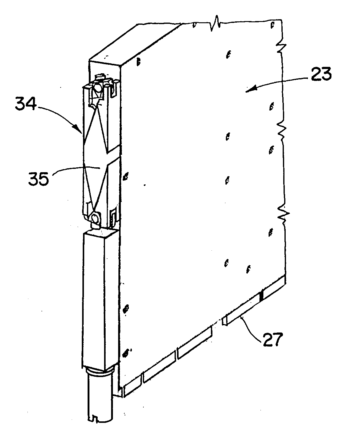
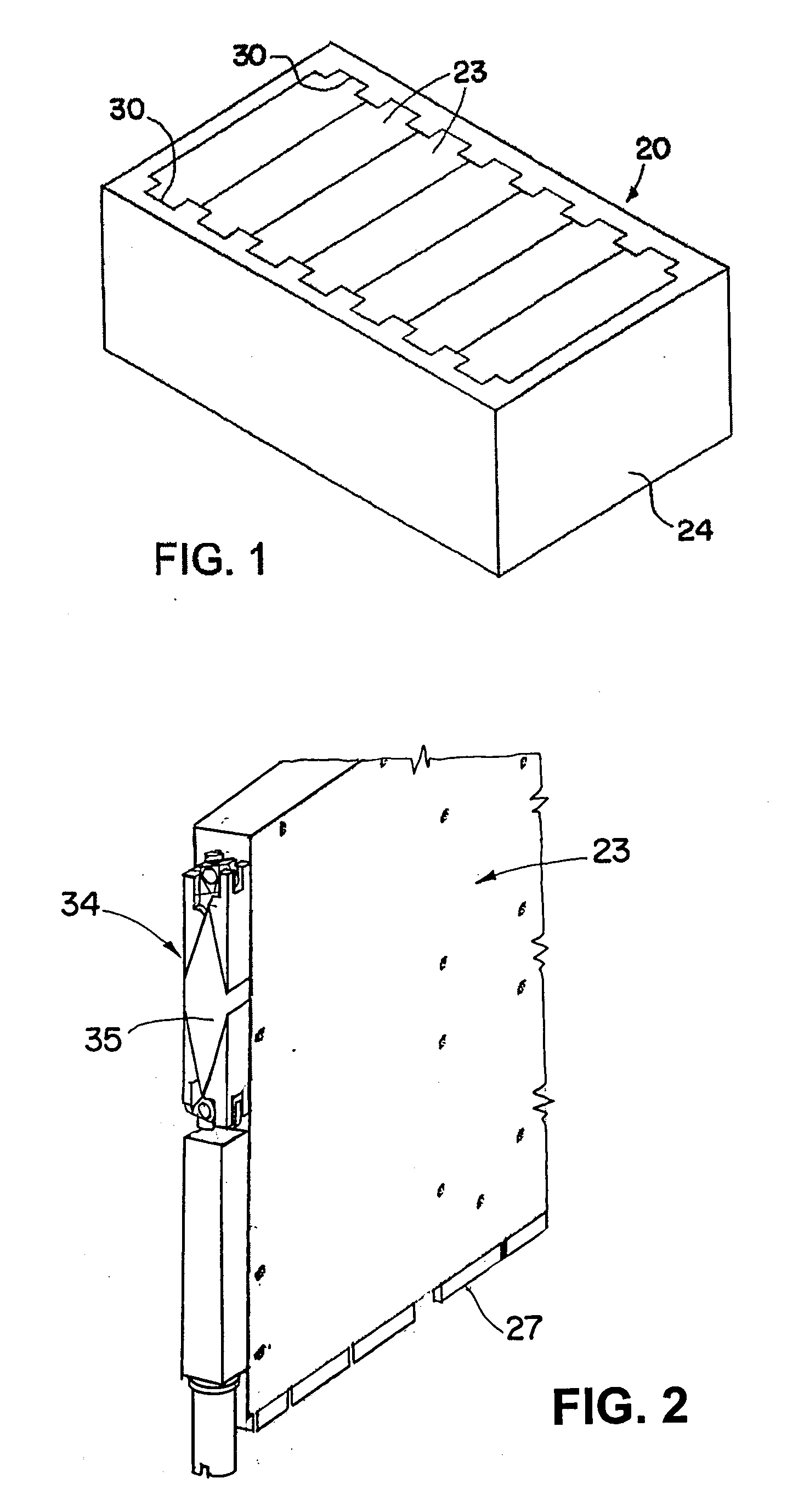
[0025]Referring now to the drawings, and initially to FIG. 1, a chassis 20 has plugged therein one or more electronic modules 23. The electronic modules 23 may be of a type, such as circuit board modules or modules that may use air and / or liquid for cooling (or heating) electronic components contained in the modules. Such modules may have an fluid-tight interior enclosure in which the electronic components are housed. The electronic components may be mounted to one or more circuit boards in the modules, and a single circuit board can be viewed as a simple form of a module. More commonly the modules will include one or more circuit boards enclosed in a rigid cube-like housing.

[0026]The electronic modules may be arranged in one or more rows, or in different patterns as may be desired. The chassis may be in the form of an open-sided enclosure that has at the blind side thereof, electrical connectors (not shown) that mate with electrical connectors 27 of the modules to establish an elec...


PUM


Abstract

A wedge lock clamping assembly, system and method wherein the module to be clamped in a slot in a chassis has a pair of wedge surfaces oppositely inclined to spaced-apart side surfaces of the slot. The clamping assembly comprises a pair of wedge elements on opposite sides of a movement axis and each wedge element is configured to be disposed within the slot between a respective wedge surface of the module and a respective side surface of the slot. An actuator operates to forcibly urge the wedge elements along the movement axis for causing the wedge elements to be wedged between the respective wedge surfaces of the module and respective side surfaces of the slot for clamping the module in the slot. A toggle is interposed between the wedge elements and the actuator for equalizing the force acting on each wedge element such that the wedge elements will move axially relative to one another to accommodate any difference in gap widths between the wedge surfaces of the module and side surfaces of the slots thereby to minimize any lateral shifting of the module relative to the slot while still securing clamping the module in the slot.

Description

RELATED APPLICATION[0001]This application claims the benefit of U.S. Provisional Application No. 60 / 807,663 filed Jul. 18, 2006, which is hereby incorporated herein by reference in its entirety.FIELD OF THE INVENTION[0002]The invention herein described relates generally to clamp systems for clamping a movable component between spaced apart surfaces, and more particularly to such systems for clamping electronic modules within slots in a chassis of a rack or sub-rack, including in particular fluid-cooled electronic modules and chassis assemblies with transition sensitive connectors.BACKGROUND[0003]A commonly used electronic packaging process is for electrical “daughter” modules, such as circuit boards or modules, to be plugged perpendicularly into respective connectors on a “motherboard”. The term motherboard is often used synonymously with the term backplane to describe a circuit board that contains general circuitry and connectors into which other circuit boards or modules can be pl...

Claims


Application Information

Patent Timeline
Patent Type & Authority Applications(United States)
IPC IPC(8): H05K7/12
CPCH05K7/1404G06F1/183
Inventor HARVEY, REX J.FRINDT, ROBERT A.
Owner PARKER INTANGIBLES LLC
Learn More