Underwater light

Active Publication Date: 2008-10-02
HAYASHIBARA CO LTD
View PDF5 Cites 13 Cited by
  • Summary
  • Abstract
  • Description
  • Claims
  • Application Information

AI Technical Summary

Benefits of technology

[0005]It is a major object of the present invention to provide an excellently watertight, highly stable underwater light that mounts watertight walls on screw holes to provide stable electric power for preventing the generation of current leakage or poor electrical conduction caused by contact between power wires and water when mounted underwater.
[0006]In order to achieve the foregoing object, the present invention discloses an underwater light, which generally has a base having a light source housing chamber and a bottom tunnel. The base has at least two screw holes that communicate the light source housing chamber with the bottom tunnel. A substrate for a light-emitting device is dis

Problems solved by technology

However, a largest potential issue for the underwater light is the problem of water penetration.
The commercial underwater light usually has poor e

Method used


Image

  • Underwater light
  • Underwater light
  • Underwater light

Examples


Embodiment Construction

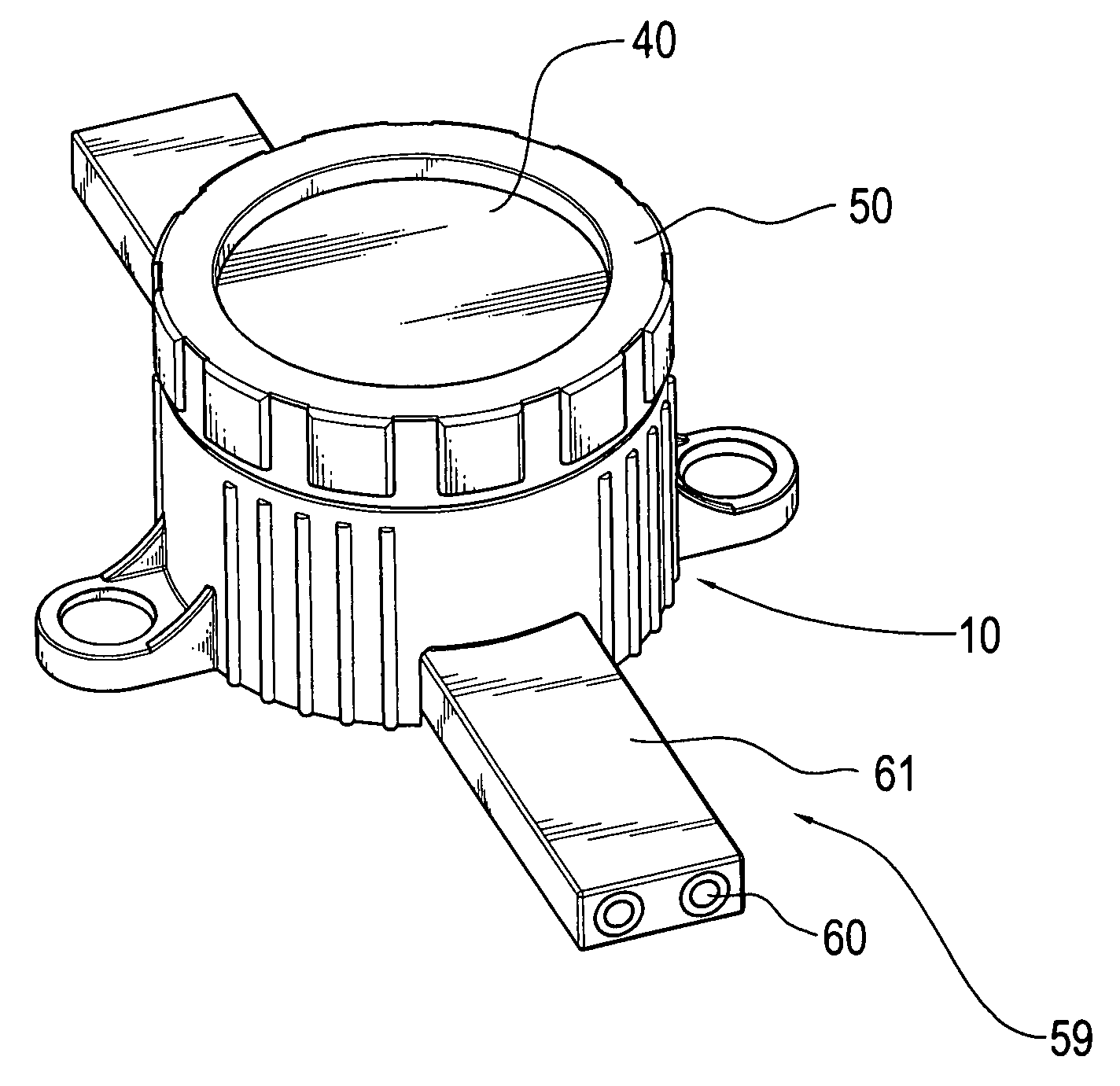
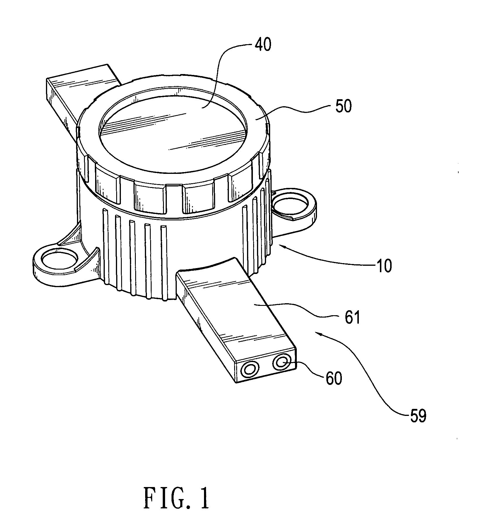
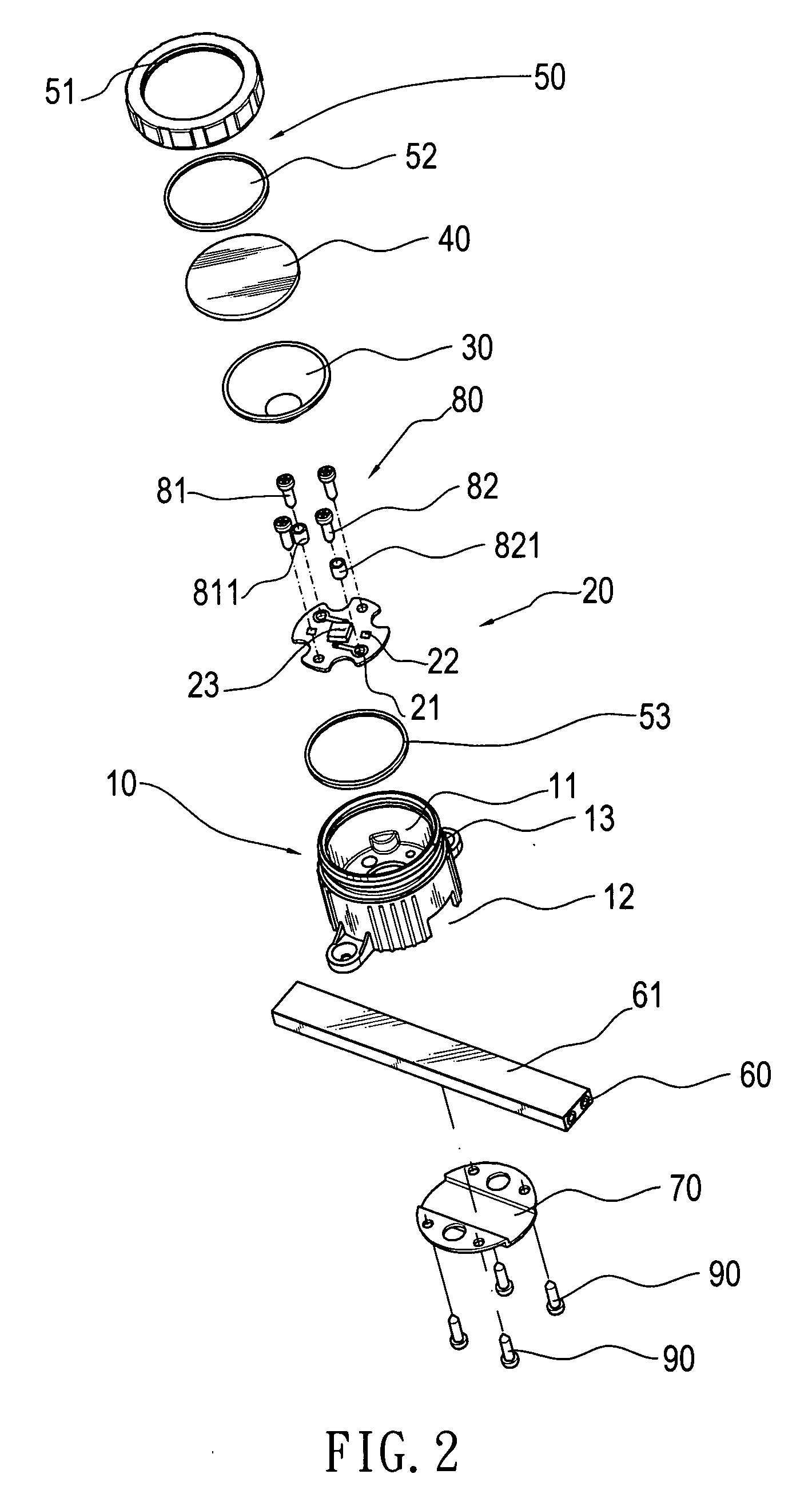
[0012]Referring to FIGS. 1 through 3, an underwater light of the present invention comprises a base 10, a substrate 20 for a light-emitting device, a reflection cover 30, a watertight upper cover 50, a power strip 59, a bottom plate 70 and at least two screw devices 80. The base 10 has a light source housing chamber 11 and a bottom tunnel 12. At least two screw holes 14 are formed inside the light source housing chamber 11 to communicate with the bottom tunnel 12, wherein two screw holes are utilized in this preferred embodiment. In addition, a coupling part 13 is mounted on the upper edge of the light source housing chamber 11. The substrate 20 is mounted on the inside of the light source housing chamber 11 of the base 10. In addition, the substrate 20 has a connection circuit 21, an electronic device 22 and at least one light-emitting device mounted thereon. The light-emitting device is such as a light-emitting diode 23 or a light bulb. The reflection cover 30 is located over the ...


PUM


Abstract

An underwater light generally has a base having a light source housing chamber and a bottom tunnel. The base has at least two screw holes communicating the light source housing chamber with the bottom tunnel. A substrate for a light-emitting device is disposed in the light source housing chamber. A reflection cover is disposed over the substrate. A watertight upper cover is disposed over the reflection cover, and coupled to the upper edge of the light source housing chamber. The screw holes are connected respectively with two watertight walls to allow the insertion thereinto of at least two screw devices. A power strip is clamped in the bottom tunnel by a bottom plate to enable the watertight walls to pierce through an insulating casing of the power strip for electrifying the screw devices, whereby the underwater light has a stable power source and an excellent property of watertightness.

Description

FIELD OF THE INVENTION[0001]The present invention relates to an excellently watertight, highly stable underwater light to be suitable for use in swimming pools, water pools, aquariums and fountains.BACKGROUND OF THE INVENTION[0002]Nowadays, the products such as candy, crackers and gift boxes are laid stress on their packages. In addition, for the purpose of creating more features and pleasant scenes to attract many tourists or pleasure the owners or other people, many colorful and beautiful decorative lights adaptable to beautify the appearance at night time are applied to scenic spots, residential environments and public places.[0003]Among such decorative landscape lights, which are applied to water dance and pools, the underwater lights are applied to the swimming pools, the water pools, the aquariums and the fountains. There is an increased tendency to apply the light-emitting diode, which acts as the light source, to the underwater light. The light-emitting diode has long durabi...

Claims


Application Information

Patent Timeline
IPC IPC(8): F21V33/00
CPCF21S8/00F21V21/002F21V31/00F21W2131/401
Inventor LIN, YUAN
Owner HAYASHIBARA CO LTD
Why Eureka
Try Eureka