

Fan and impeller thereof
- Summary
- Abstract
- Description
- Claims
- Application Information
AI Technical Summary
Benefits of technology
Problems solved by technology
Method used
Image

Examples
Embodiment Construction
[0017]The present invention will be apparent from the following detailed description, which proceeds with reference to the accompanying drawings, wherein the same references relate to the same elements.
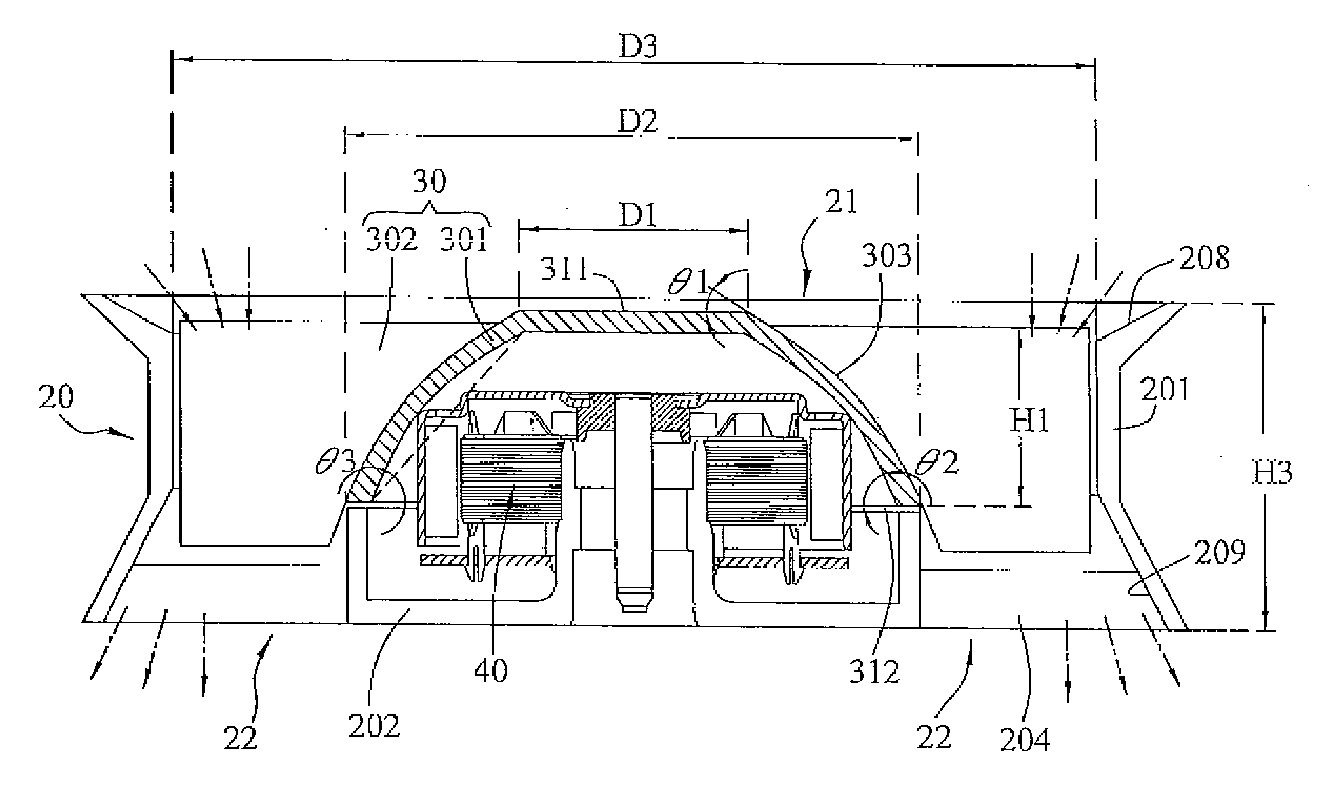
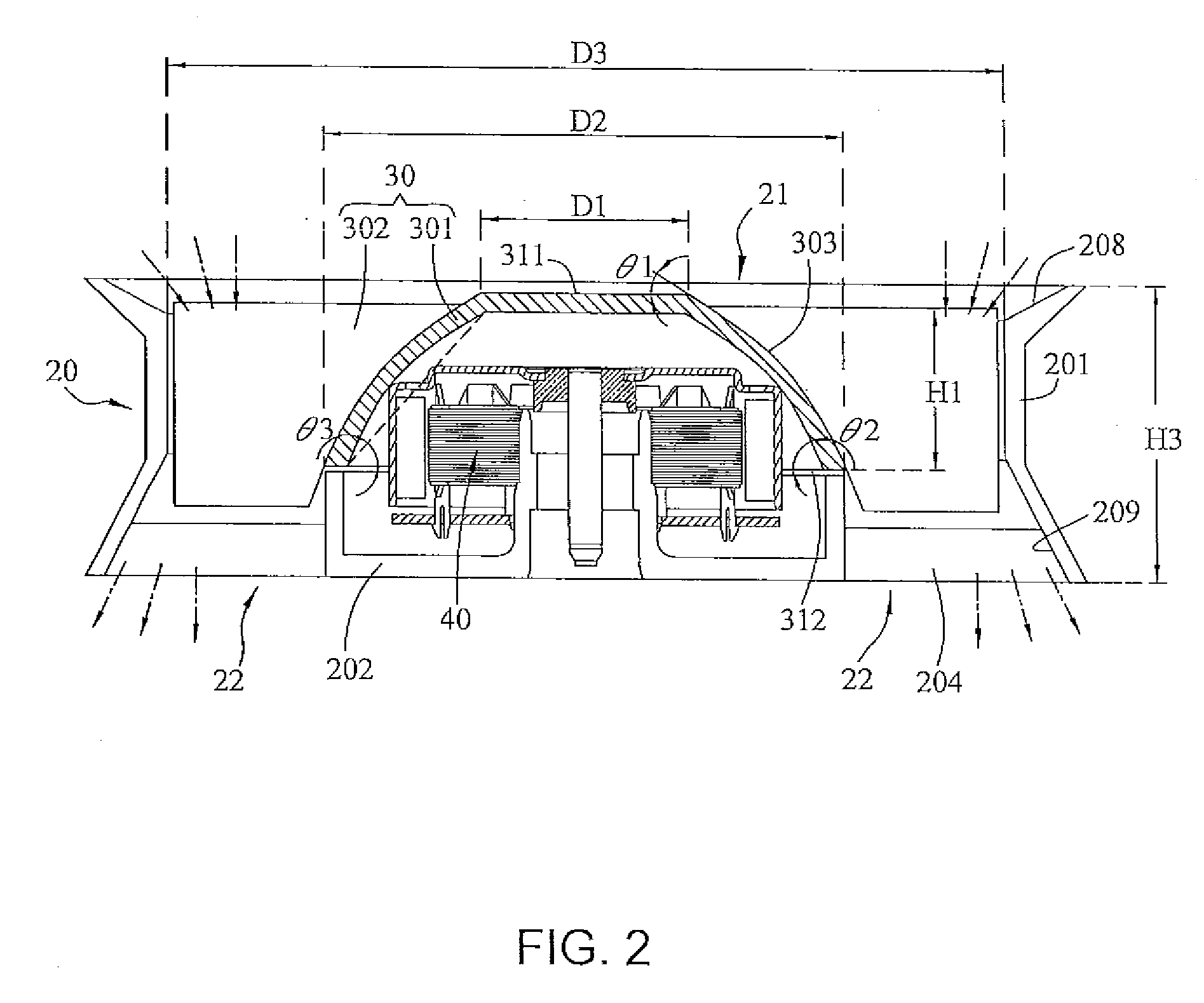
[0018]FIG. 2 is a cross-sectional view of a fan according to an embodiment of the present invention. Referring to FIG. 2, a fan 2, which is preferably an axial-flow fan, includes a fan frame 20, an impeller 30 and a motor 40. The impeller 30 and the motor 40 are disposed within the fan frame 20. The fan frame 20 includes a main body 201 with a through hole to form an inlet 21, and an outlet 22. The fan frame can have a roughly square, circular; elliptical or rhombus shape. Furthermore, the fan frame 20 includes a base 202 and at least one connecting element 204. The base 202 is preferably disposed near the outlet 22 of the fan 2. The connecting element 204 is disposed between the main body 201 and the base 202 for supporting the base 202. In this embodiment, the connecting element 204...
PUM
 Abstract
Description
Claims
Application Information