Transmission Directional Antenna Control System, Base Station, And Transmission Directional Antenna Control Method Used For System And Base Station

Inactive Publication Date: 2008-10-02
NEC CORP
View PDF10 Cites 30 Cited by
  • Summary
  • Abstract
  • Description
  • Claims
  • Application Information

AI Technical Summary

Benefits of technology

[0023]The present invention can obtain the advantages of being able to select the most appropriate beam...

Problems solved by technology

However, there is a problem in that, at the receiving side of a base station, another user's signal simultaneously that contacts the s...

Method used


Image

  • Transmission Directional Antenna Control System, Base Station, And Transmission Directional Antenna Control Method Used For System And Base Station
  • Transmission Directional Antenna Control System, Base Station, And Transmission Directional Antenna Control Method Used For System And Base Station
  • Transmission Directional Antenna Control System, Base Station, And Transmission Directional Antenna Control Method Used For System And Base Station

Examples


Embodiment Construction

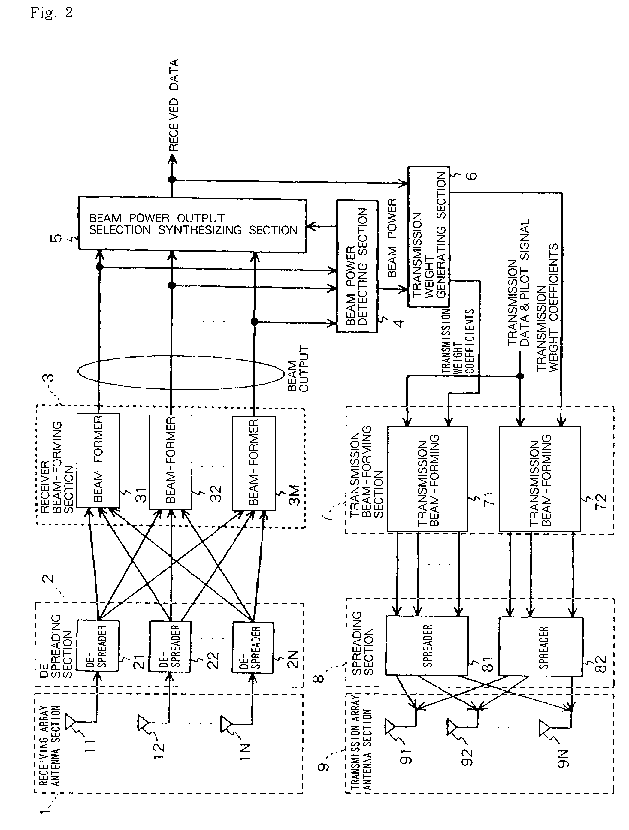
[0050]Next, embodiments of the present invention will be described with reference to the drawings. FIG. 2 is a block diagram showing a constitution of a base station according to one embodiment of the present invention. In FIG. 2, a base station according to one embodiment of the present invention constitutes a transmission directional antenna control system together with an unillustrated mobile station, and is constituted by receiving array antenna section 1, de-spreader 2, receiver beam-forming section 3, beam power detecting section 4, beam output selection synthesizing section 5, transmission weight generating section 6, transmission beam-forming section 7, spreader 8, and transmission array antenna section 9.

[0051]Receiving array antenna section 1 is comprised of N pieces (N is an integer of two or more) of array antenna elements 11 to 1N, and de-spreading section 2 is comprised of N pieces of de-spreaders 21 to 2N. Receiver beam-forming section 3 is comprised of M pieces (M is...


PUM


Abstract

To provide a base station capable of selecting an optimum beam from among transmitted ones of multi-beams. In the arrangement, a beam power determining part (4) determines M received signal powers of multi-beams, and a beam output selecting part (5) selects, based on the information of the received powers from the beam power determining part (4), a beam of the largest power from among M outputs of beam formers (31-3M), and receives the selected beam. A transmission weight generating part (6) selects, based on the received information, a beam corresponding to the signal of a spread code selected by a mobile station and also selects another any beam to notify their respective transmission weighting coefficients. A transmitted beam forming part (7) weights transmitted data corresponding to transmission array antenna elements (91-9N) with the transmission weighting coefficients. Spreaders (81,82) use respective different spread codes to spread input signals, and the transmission array antenna elements (91-9N) send the beam-formed signals.

Description

TECHNICAL FIELD[0001]The present invention relates to a transmission directional antenna control system, a base station, and a transmission directional antenna control method used for the system and base station, and in particular, it relates to a control method of directivity when transmitting a downward electric wave by a plurality of transmission array antenna elements used for the base station.BACKGROUND ART[0002]In a CDMA (Code Division Multiple Access) system, there is a potential of being able to increase a subscriber capacity, and the system is applied as a radio access system of the next generation mobile communication cellular system.[0003]However, there is a problem in that, at the receiving side of a base station, another user's signal simultaneously that contacts the same carrier causes an interference, and at the receiving side of a mobile station, a signal transmitted to another user causes interference.[0004]As a method for eliminating these interferences, there is a...

Claims


Application Information

Patent Timeline
IPC IPC(8): H04B7/02H04B7/005H04B7/06
CPCH01Q3/2605H04B1/707H04B7/0617H04W52/42
Inventor KIKUCHI, TOHRU
Owner NEC CORP
Why Eureka
Try Eureka