Clamp band for spring brakes

a technology of spring brakes and clamping bands, which is applied in the direction of braking systems, braking components, machines/engines, etc., can solve the problems of no longer securely fastening of the diaphragm, no longer keeping the spring in place, and injuring or killing anyone in the surrounding area, so as to save manufacturing costs, reduce raw materials, and simple and reliable construction

Inactive Publication Date: 2008-10-09
METRO BEARING & AUTOMOTIVE
View PDF5 Cites 1 Cited by
  • Summary
  • Abstract
  • Description
  • Claims
  • Application Information

AI Technical Summary

Benefits of technology

[0013]It is an object of the present invention to provide a clamp band formed by two semicircle clamp bands which requires less amount of raw materials for manufacturing the clamp band and thereby saving manufacturing costs.
[0014]It is an object of the present invention to provide a clamp band for spring brakes which can securely engage the two chambers to prevent the spring, the diaphragm and the second chamber from bursting out of the first chamber, causing damage to properties and / or injuries to anybody in the surrounding area.
[0015]It is a further object of the present invention to provide a clamp band for spring brakes which is of simple and reliable construction.
[0016]It is another further object of the present invention to provide a clamp band for spring brakes which is formed by two semicircle clamp bands and so requires less amount of raw materials for manufacturing the clamp band. The clamp band is therefore susceptible of a low cost of manufacture with regard to both materials and labor, and which accordingly is then susceptible of low prices of sale to the consuming public, thereby making such device economically available to the buying public.
[0017]An even further object of the present invention is to provide a clamp band for spring brakes which is readily applicable for existing conventional spring brakes.

Problems solved by technology

However, if a user inadvertently loosens or disassembles the clamp band by loosening a screw thereon, or if the clamp band is loosened accidentally owing to, for example, a bump to the vehicle, or if the clamp band becomes out of order and fails to engage the chambers properly, the diaphragm is no longer securely fastened and thus can no longer keep the spring in place.
In such a case, anybody in the surrounding area may be injured or even killed by the parts bursting away from the first chamber, let alone damage is likely to be caused to properties in the neighborhood.
Although such arrangement can prevent any accidental disengagement of the two chambers, it is susceptible of higher production costs and lower manufacturing efficiency.
Moreover, if any component has any defect or if there is any error or abnormality during the assembling procedures, the air brake may fail to function properly and may not be repaired and will have to be disposed of, which results in a waste of resources.

Method used


Image

  • Clamp band for spring brakes
  • Clamp band for spring brakes
  • Clamp band for spring brakes

Examples


Embodiment Construction

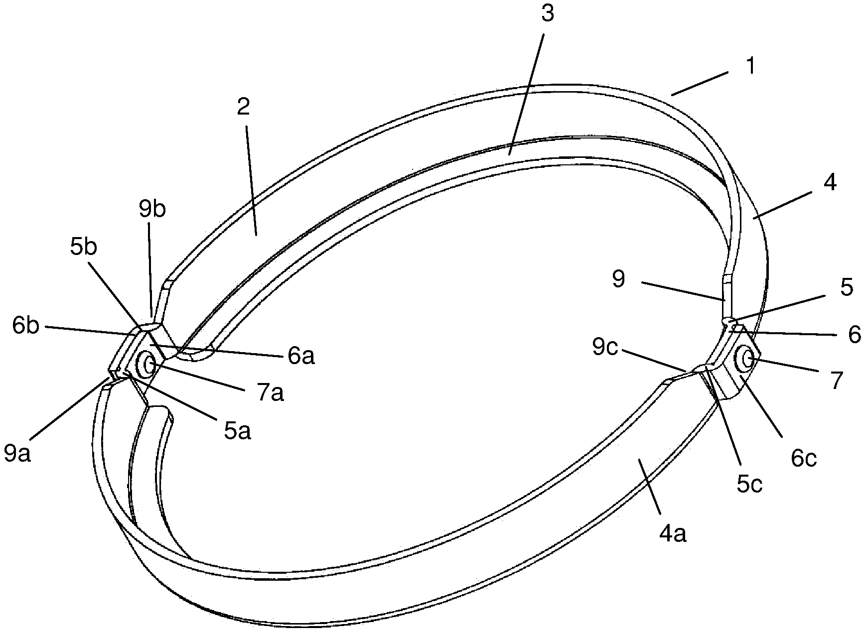
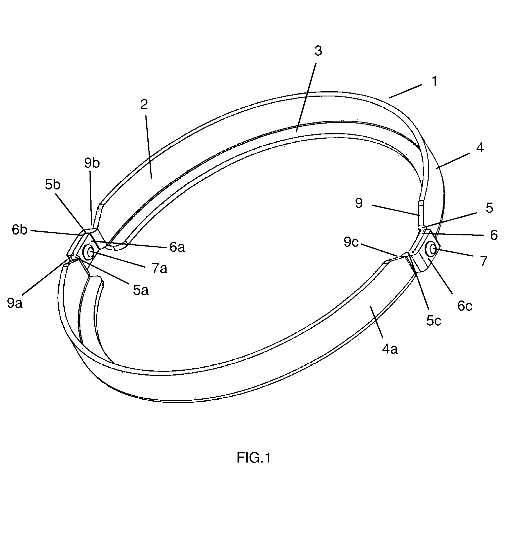
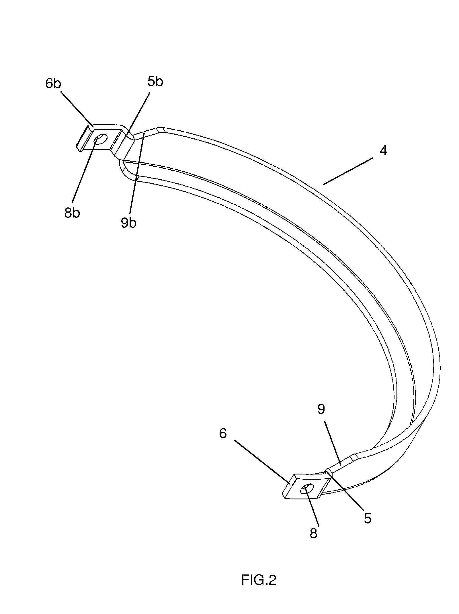
[0023]As illustrated in FIG. 1 to FIG. 5, the present invention generally comprises an annular clamp band 1 pre-formed with a side wall 2 and a rim 3 extending perpendicularly from a first end thereof. The annular clamp band 1 comprises a first clamp band 4 and a second clamp band 4a having identical semi-annular shape, and each of the first clamp band 4 and the second clamp band 4a has a first end with a first connecting plate 5, 5a extended outward therefrom to connect to a first welding plate 6, 6a and a second end with a second connecting plate 5b, 5c extended outward therefrom to connect to a second welding plate 6b, 6c. The first clamp band 4 and the second clamp band 4a are connected to form the annular clamp band 1 by joining the first welding plate 6 of the first clamp band 4 with the second welding plate 6c of the second clamp band 4a and the second welding plate 6b of the first clamp band 4 with the first welding plate 6a of the second clamp band 4a respectively. The firs...


PUM


Abstract

A clamp band for spring brakes which comprises an annular clamp band pre-formed with a side wall and a rim extended perpendicularly from a first end thereof, wherein during assembling of a spring brake when an edge of a first chamber, a diaphragm and an edge of a second chamber are positioned in sequential order on the rim a second end of the side wall is deformed to bend inwards to encompass the edge of the second chamber to secure the edges of the two chambers and the diaphragm in place. The annular clamp band comprises a first clamp band and a second clamp band having identical semi-annular shape.

Description

BACKGROUND OF THE INVENTION[0001]The present invention relates to a clamp band for vehicle brakes and more particularly pertains to a clamp band for spring brakes which prevents the disengagement of the two chambers.[0002]A conventional spring brake generally comprises a first chamber, a second chamber, a diaphragm, a spring and a pushrod connecting to a braking device such as a brake shoe or brake pad. The diaphragm is placed between the two chambers. The spring is heavily coiled between the diaphragm and the bottom of the first chamber. By controlling the amount of air pressure applied to the diaphragm and thereby controlling the compression of the spring, the driver can apply or release the brake. As a significant amount of energy is stored in the coiled spring, it is vital to hold the two chambers and the diaphragm in place to prevent the spring from bursting out of the first chamber.[0003]Double diaphragm spring brakes are also available in the marketplace. A conventional doubl...

Claims


Application Information

Patent Timeline
Patent Type & Authority Applications(United States)
IPC IPC(8): A44B21/00A44B99/00
CPCY10T24/44B60T17/088
Inventor CHOW, LAI YEE
Owner METRO BEARING & AUTOMOTIVE
Why Eureka
Try Eureka