Device for fastening an auxiliary part to a weapon by a magnet

a technology of auxiliary parts and magnets, which is applied in the direction of sighting devices, weapon components, weapons, etc., can solve the problems of inability to significantly improve the work efficiency the inability to mount suitable fastening devices to the usually valuable weapon, and the inability to achieve significant constructive rework. , to achieve the effect of convenient replacement of the auxiliary part, simple and cost-effective construction of the fastening device, and sufficient precise orientation of the auxiliary parts

Inactive Publication Date: 2008-10-09
KILIC MICHAEL ALI
View PDF13 Cites 19 Cited by
  • Summary
  • Abstract
  • Description
  • Claims
  • Application Information

AI Technical Summary

Benefits of technology

[0007]On the basis of this prior art, it is the object of the present invention to provide a device which allows the fastening of an auxiliary part, in particular a targeting unit or the like, to a weapon which has ferromagnetic parts, without permanent reworking being necessary on the weapon. The present invention particularly allows a simple and cost-effective construction of a fastening device and allows a sufficiently precise orientation of the auxiliary part on the weapon. Furthermore, the device allows easy replaceability of the auxiliary part, so that especially flexible retrofitting possibilities of the weapon are opened up. Furthermore, the weapon may be returned to its original state by simple and tool-free removal of the fastening device. The present invention also enables the simultaneous fastening of multiple auxiliary parts to a weapon, by attaching more than one fastening device to the weapon.

Problems solved by technology

However, firstly there is the need for adding further auxiliary parts to weapons whose base plates are already occupied by existing auxiliary parts, or attaching auxiliary parts to weapons which have no base plate or no suitable base plate for fastening.
The subsequent mounting of suitable fastening devices to a usually valuable weapon is very complex and costly and is impossible in many cases without significant constructive rework.

Method used


Image

  • Device for fastening an auxiliary part to a weapon by a magnet
  • Device for fastening an auxiliary part to a weapon by a magnet
  • Device for fastening an auxiliary part to a weapon by a magnet

Examples


exemplary embodiment 01

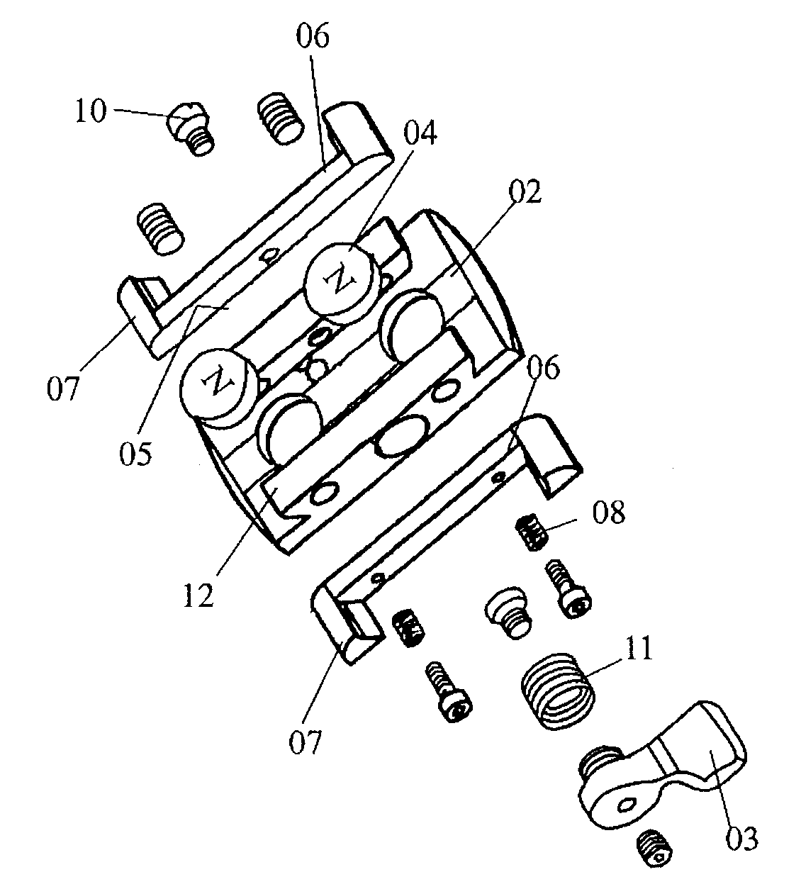
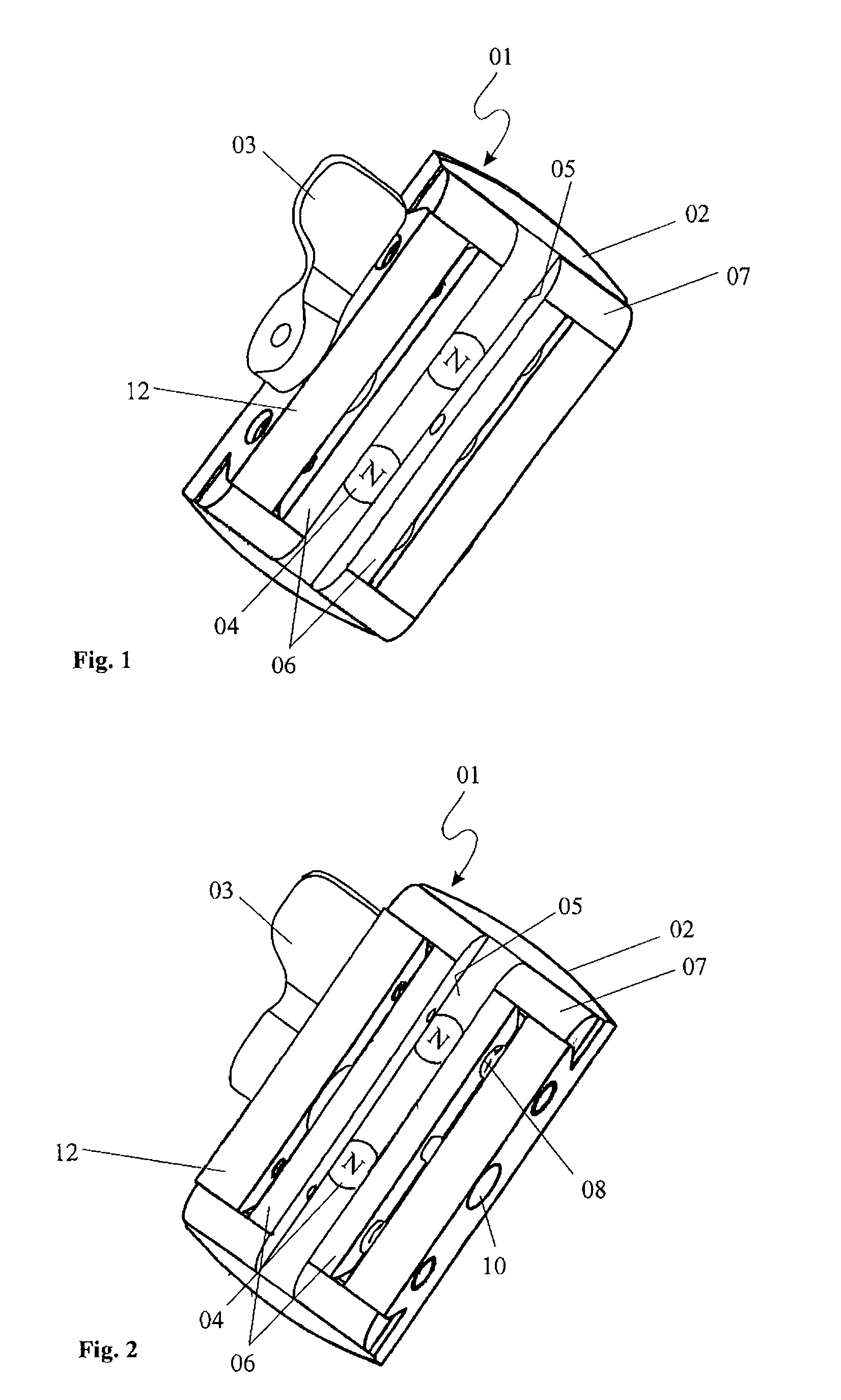
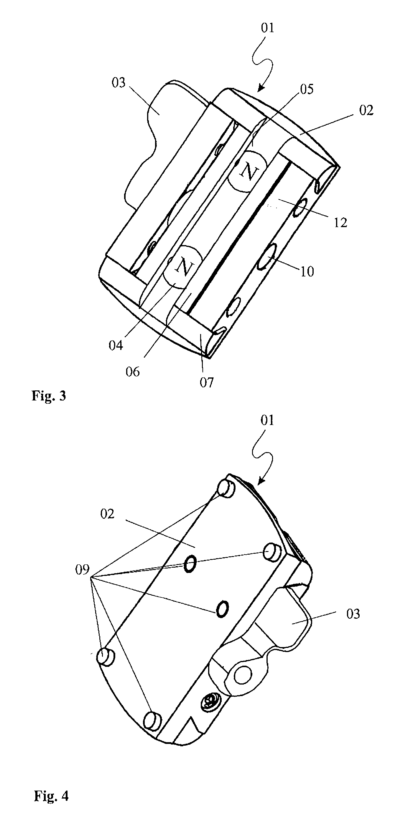
[0032]FIGS. 1 through 5 show various perspective views of a first exemplary embodiment 01 of the fastening device according to the present invention. The fastening device 01 comprises a base plate 02, which has dovetail edges 12 on its two long sides. As shown in FIG. 4, various fastening elements 09 are located on the top side of the base plate 02, which are used for fastening auxiliary parts 19 such as a telescopic sight, an illumination unit, or a rangefinder device. These fastening elements 09 comprise locking and orientation pins as well as threaded holes, into which the auxiliary part may be screwed using screws. The locking pins are used for precise orientation of the auxiliary part 19 on the base plate 02 of the fastening device 01. Two clamping jaws 06 are guided on the dovetail edges 12 of the base plate 02, the clamping jaws 06 having dovetail guides 07, which are guided in the dovetail edge 12. The clamping jaws 06 have friction-increasing coatings 05 on their clamping j...

exemplary embodiment 14

[0040]FIG. 9 shows a second exemplary embodiment 14 of a fastening device according to the present invention in the barrel direction of a weapon. The fastening device 14 comprises a base plate 15, as well as two clamping jaws 16 extending opposite to one another along the barrel rail, which enclose both the barrel rail 20 and also parts of the double barrel 13 of a hunting rifle. The double barrel 13 of the hunting rifle is used on one hand for firing projectile ammunition, and on the other hand for firing shot, and has both a rifled barrel and also a smooth barrel.

[0041]FIG. 10 shows a side view of the second exemplary embodiment of the fastening device 14, various fastening elements for accommodating an auxiliary part being recognizable on the base plate 15. The clamping jaw 16 is attached to the base plate 15 with the aid of screws, and has a top magnetic strip 17 and a bottom magnetic strip 18. The top magnetic strip 17 is used for the magnetic fastening of the fastening device ...


PUM


Abstract

The present invention relates to a device (01, 14) for fastening an auxiliary part (19), in particular a targeting unit or the like, to a weapon, which has at least one ferromagnetic part, the device comprising a base plate (02, 15), to which the auxiliary part (19) may be fastened, and the device (01, 14) being fixed on the weapon by at least one magnet (04).

Description

CROSS-REFERENCE TO RELATED APPLICATIONS[0001]The present patent application claims priority from German Patent Application No. 20 2006 015 136.2, filed on Sep. 29, 2006.BACKGROUND OF THE INVENTION[0002]The present invention relates to a device for fastening an auxiliary part, in particular a targeting unit or the like, to a weapon according to the teaching of Claim 1.[0003]Fastening devices of the generic type are used, for example, but not exclusively, for fastening targeting units, such as telescopic sights or other optical targeting aids, to a weapon, such as a hunting or sporting rifle. However, attaching other auxiliary parts such as rangefinders, illumination units, or night vision devices to such a fastening device is also conceivable.[0004]For this purpose, it is known from the prior art that the weapon per se is provided with a fastening device of the generic type, which is provided in most cases on the barrel as a base plate or mounting plate. In many cases, such a fasteni...

Claims


Application Information

Patent Timeline
Patent Type & Authority Applications(United States)
IPC IPC(8): F41G1/00
CPCF41G1/387F41G11/003F41G11/004
Inventor KILIC, MICHAEL ALI
Owner KILIC MICHAEL ALI
Why Eureka
Try Eureka