Coupling element for a shackle

a coupling element and shackle technology, applied in the direction of chain elements, driving chains, chain fastenings, etc., can solve the problems of increasing manufacturing costs, affecting the strength properties, so as to achieve simple and cheap production and favorable strength properties

Inactive Publication Date: 2008-10-09
PENGG AGYD
View PDF5 Cites 7 Cited by
  • Summary
  • Abstract
  • Description
  • Claims
  • Application Information

AI Technical Summary

Benefits of technology

[0005]The present invention provides a shackle which is simple and cheap to produce and, in addition, has more favorable strength properties than the known shackles. This is achieved, according to the invention, with a coupling element of the type defined above in which the bores are out-of-line relatively to each other and extend at an angle to a longitudinal center line of the coupling element.

Problems solved by technology

A disadvantage of the known embodiment is primarily that it is necessary, due to their construction, to use two differently designed coupling elements, which increases the manufacturing costs considerably.
Furthermore, the connecting bolt is subjected to high bending stresses, due to its design, which causes drawbacks with respect to the strength properties.
A disadvantage of this shackle is that it involves very elaborate production, because the parts have to be forged in order to acquire the required load-bearing capacity.
However, the locking pin does not hold the two link halves together, but merely serves to prevent the teeth of the inner and outer brackets from disengaging.
A disadvantage of this embodiment is primarily that it is relatively complicated to produce by reason of the teeth on the inner and outer brackets.

Method used


Image

  • Coupling element for a shackle
  • Coupling element for a shackle
  • Coupling element for a shackle

Examples


Embodiment Construction

[0013]Certain terminology is used in the following description for convenience only and is not limiting. The terminology includes words specifically mentioned, derivatives thereof and words of similar import. The exemplary embodiment illustrated below is not intended to be exhaustive or to limit the invention to the precise form disclosed. This embodiment is chosen and described to best explain the principle of the invention and its application in practical use and to enable others skilled in the art to best utilize the invention.

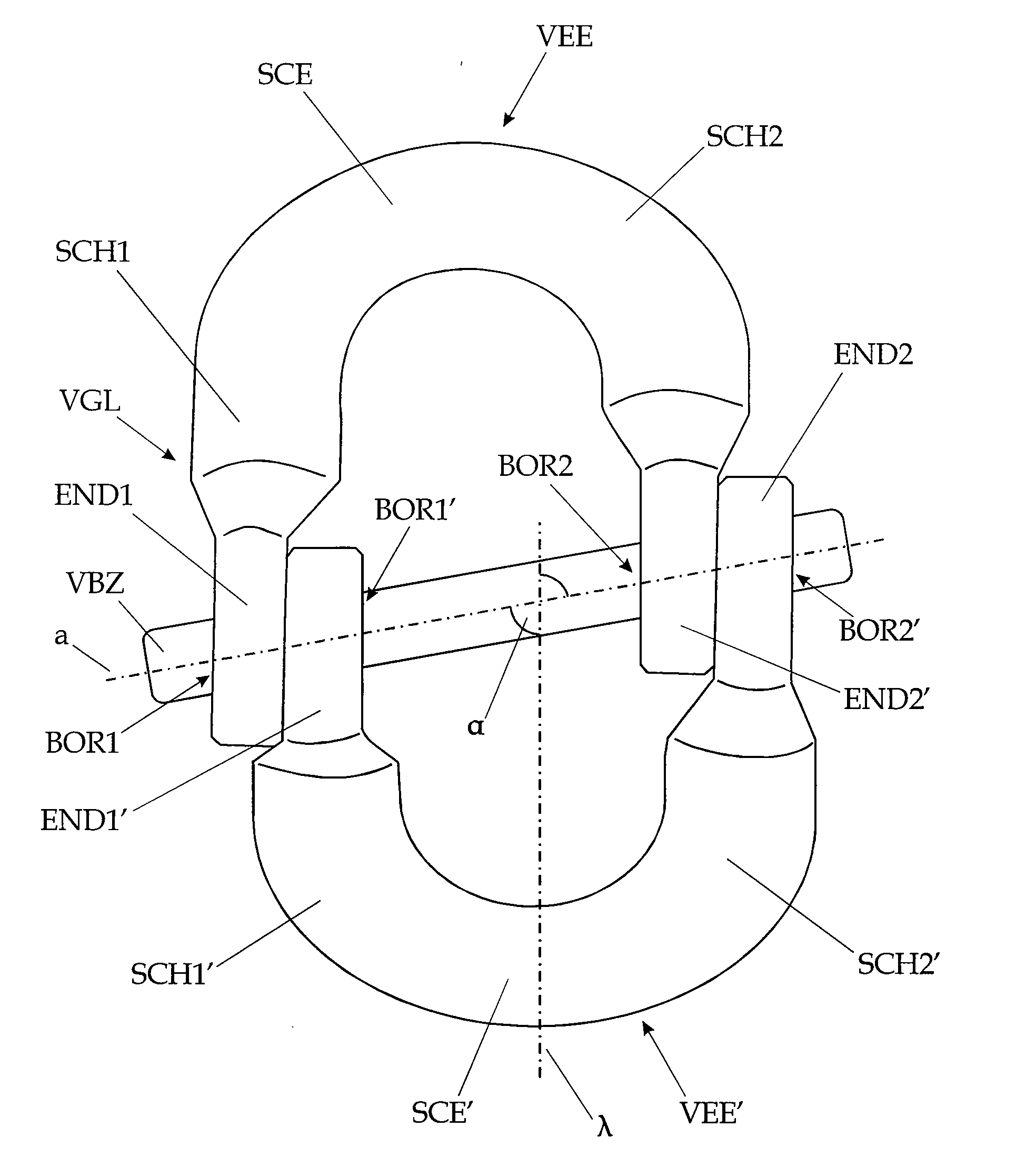
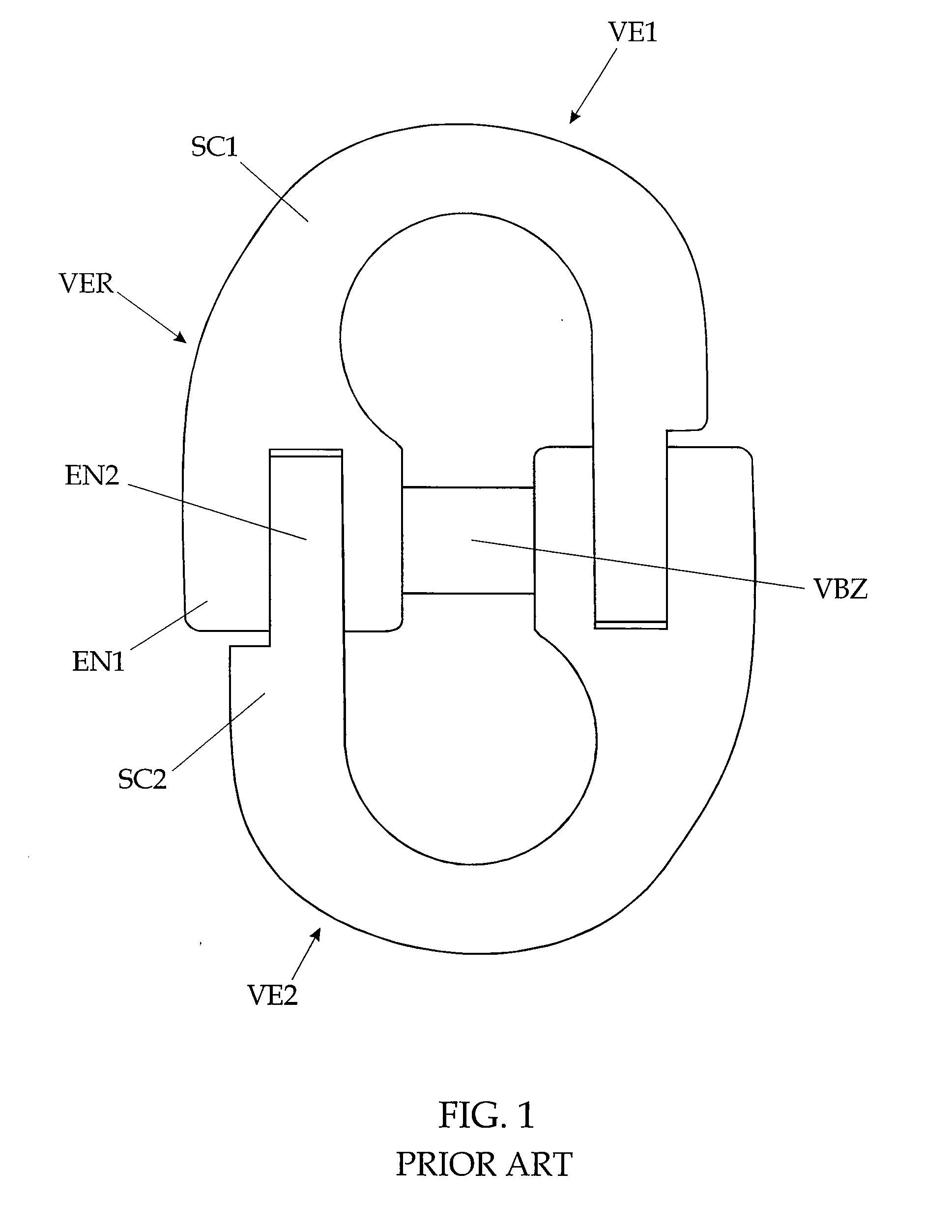
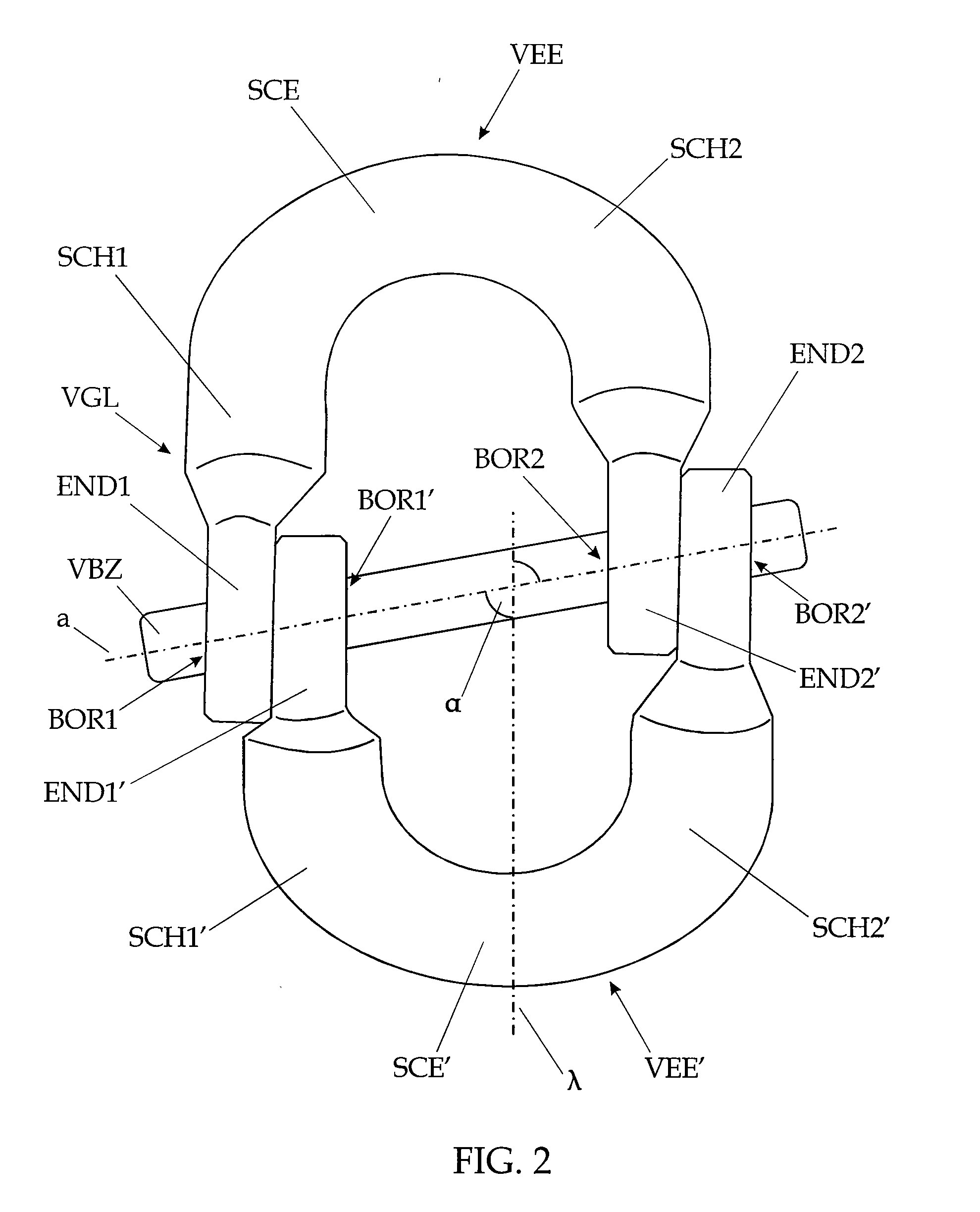
[0014]According to FIGS. 2 and 3, a shackle of the invention VGL has two coupling elements VEE, VEE′ of substantially U-shaped cross-region. Each coupling element VEE, VEE′ has a cusp region SCE, SCE′ and two legs SCH1, SCH2, SCH1′, SCH2′ extending therefrom. At each of the free ends END1, END2, END1′ END2′ of the legs SCH1, SCH2, SCH1′, SCH2′ there is provided a bore BOR1, BOR2, BOR1′, BOR2′, which bores BOR1, BOR2, BOR1′, BOR2′ of a coupling element VEE, ...


PUM


Abstract

A coupling element of a shackle for load-carrying elements, such as chains, hooks, or the like, is disclosed. The coupling element has two substantially parallel legs, whose free ends each have a bore for the accommodation of a connecting bolt, by means of which the coupling element can be linked to another coupling element of the same design to form the shackle, the coupling elements being held together only by the connecting bolt, which bores extend in the same direction relatively to each other, wherein the bores are out-of-line and extend at an angle to a longitudinal center line of the coupling element.

Description

FIELD OF THE INVENTION[0001]The invention relates to a coupling element of a shackle for load-carrying elements, such as chains, hooks, or the like, which coupling element exhibits two legs extending substantially parallel to each other and whose free ends each have a bore for the accommodation of a connecting bolt, by means of which the coupling element can be connected to another coupling element of the same design to form the shackle. The coupling elements are linked only by the connecting bolts and the bores extend in the same direction relatively to each other. Furthermore, the invention relates to a shackle having two coupling elements interconnected by means of a connecting bolt.BACKGROUND OF THE INVENTION[0002]Shackles of the present type are usually employed for connecting chains or lashing means, etc. to each other or to corresponding fittings, such as hooks, shackles, etc. EP 009 2382 discloses a shackle which has a first and a second coupling element, which elements each...

Claims


Application Information

Patent Timeline
Patent Type & Authority Applications(United States)
IPC IPC(8): F16G15/02
CPCF16G15/02F16G15/04
Inventor PENGG, AGYD
Owner PENGG AGYD
Why Eureka
Try Eureka