Resilient closure for pressure driven dispensing container

a technology of pressure-driven dispensing containers and resilient closures, which is applied in the direction of functional valves, pliable tubular containers, manufacturing tools, etc., can solve the problems of not quite so widespread, operation may be cumbersome, and the outside container must be sufficiently robust to resist deformation under relatively high pressure, etc., to achieve simple and cheaper production

Inactive Publication Date: 2019-03-19
ANHEUSER BUSCH INBEV SA
View PDF55 Cites 3 Cited by
  • Summary
  • Abstract
  • Description
  • Claims
  • Application Information

AI Technical Summary

Benefits of technology

[0030]The closure of the present invention may comprise no moving part, which makes it simple and cheaper to produce.

Problems solved by technology

It has, however, the drawback that the outer container must be sufficiently robust to resist deformation under the relatively high pressure required for the dispensing.
The solutions discussed above of storing the pressurizing gas in the container either in a small cartridge or adsorbed on a carrier are particularly suitable for smaller home appliances, but to date they are not quite so widespread yet.
But this solution has the disadvantage of having to introduce a long stem deep into the container, which operation may be cumbersome, and it is usually preferred—if possible—to control the collapse of the inner bag by other means.
The problem with the closure described therein is that if the container is retrieved from the appliance before it is empty, e.g., for mounting a new container with a different beverage or for cleaning the appliance, the liquid remaining in the container cannot be protected from contact with the ambient during storage, as the dispensing aperture of the container's closure is irreversibly open.
This may result in the degradation of the liquid still present in the container, in particular if it is a carbonated beverage such as a beer or a soda.
Furthermore, spillage of any liquid remaining in the container in case it is tilted cannot be prevented with the present closures.
These closures, however, are not suitable to operate at the pressures used in pressure dispensing containers, and in particular in case of carbonated beverages, the liquid is to be stored in the half empty container under pressure, which would unevitably open such closures.
But these valve designs are rather complex with moving parts, their production requiring cost and time extensive assembly steps, not compatible with rather disposable containers to be mounted on home appliances of rather modest size.
But the dispensing tube diameter required to ensure an acceptable flow rate of the order of 0.5 to 2.5 l / min, or even up to 5 l / min, typical of beverage dispensing containers does not allow to upscale the vial solution to pressure driven dispensing liquid containers.
This solution is not suitable for the closure of pressure driven dispensing container because (a) it comprises multiple components to be assembled which is not compatible with the cost requirement of a beverage dispensing system, and (b) the pushed open lid remains in contact with the opening of the pump tube, which is no problem when the fluid flow pushes the lid away from the tube as is the case with a pump, but is unsuitable when the liquid flow pushes the lid back against the tube as is the case with a dispensing container, thus partially obturating the dispensing pipe inlet and disrupting the liquid flow out of the container.
This valve is designed for use with inflatable products having no rigid wall and is not suitable for use with closures for dispensing containers.
Here again, the valve disclosed therein is not suitable for the closure of a dispensing container because rather large in dimensions, and requiring welding and assembly of multiple components, which is not consistent with the economics of beverage dispensing containers.

Method used


Image

  • Resilient closure for pressure driven dispensing container
  • Resilient closure for pressure driven dispensing container
  • Resilient closure for pressure driven dispensing container

Examples


first embodiment

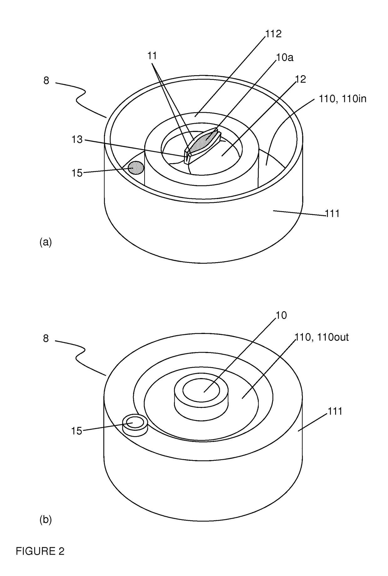
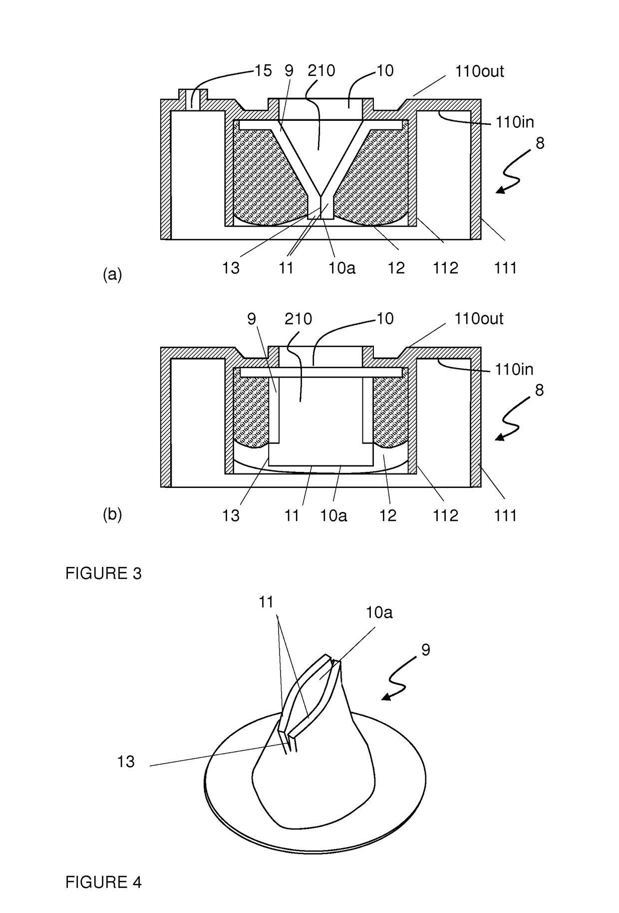
[0067]The valve (9) and resilient means (12) may be produced separately or simultaneously as explained below. In a first embodiment, the flexible valve (9) may either be injected and formed onto the inner surface (110in) of the closure, or a separately produced valve (9) may be positioned on top of the inner surface (110in). In both cases, the flexible valve (9) shall define an interior passageway (210) having a first opening at one end adjacent to and in fluid communication with the first dispensing aperture (10) and having a second opening (10a) at the other end of the passageway. An embodiment of such separately manufactured valve (9) is illustrated in FIG. 4, preferably comprising a peripheral flange allowing to fix it in position upon injection of the resilient means against the inner surface (110in) of the planar surface (110) in communication with the first aperture (10). Various designs of valves suitable for the present invention are described in US2007 / 0138189 disclosing a...

second embodiment

[0070]In a second embodiment, the valve is formed together with the resilient means, by a single injection of polymeric material comprising a foaming agent. It was observed that the foam density being higher at the surfaces contacting the tool walls and in restricted or narrow regions of the mould than in the bulk of the foam, it was possible to form with a single injection of a single expanding material the valve (9) and resilient means (12), the valve (9) having two lips (11) and a passageway (210) with walls of density higher than the density of the bulk forming the resilient means (12). In this configuration the resilient means (12) are separated from the valve by an interphase rather than an interface, wherein the density of the foam progressively increases. This embodiment is particularly advantageous in terms of production rate, production cost, and recyclability of the closure over any other closure comprising a resilient valve for gas driven dispensing containers on the mar...


PUM

PropertyMeasurementUnit
pressureaaaaaaaaaa
pressureaaaaaaaaaa
flow rateaaaaaaaaaa

Abstract

The invention is a closure for the aperture of a pressure driven dispensing container. The closure includes (a) an outer shell having a planar base including an outer first main surface and an inner second main surface. The base includes a dispensing aperture fluidly connecting the outer surface to the inner surface and receives a dispensing tube. An outer peripheral skirt juts out of the inner surface and seals the closure to the aperture of the container. The closure also includes (b) a flexible valve in contact with the inner surface located within the outer peripheral skirt and defining an interior passageway having a first opening at one end adjacent to and in fluid communication with the first dispensing aperture and having a second opening at the other end of the passageway, wherein the flexible valve is resiliently biased so that it naturally shuts and seals the second opening.

Description

[0001]This Application is the U.S. National Phase of International Application Number PCT / EP2011 / 061224 filed on Jul. 4, 2011, which claim priority to European Application Number 10168970.1 filed on Jul. 8, 2010.FIELD OF THE INVENTION[0002]The present invention relates to the field of dispensing devices for liquids, in particular of pressure driven beverage dispensing apparatuses. In particular, it concerns a closure allowing the protection of the liquid contained in a container from ambient air upon successive insertions and retrievals of the container from a dispensing unit.BACKGROUND OF THE INVENTION[0003]Liquid dispensing devices have been on the market for ages. In particular, pressure driven dispensing devices rely on a pressurized gas raising the pressure to a level of about 0.1 to 15 bar, usually of 0.5 to 1.5 bar above atmospheric in the interior of a container containing the liquid to be dispensed, such as a beverage like beer or other carbonized beverages. Since the liqui...

Claims


Application Information

Patent Timeline
Patent Type & Authority Patents(United States)
IPC IPC(8): B67D1/00F16K15/14B65D51/24B67D1/08
CPCB65D51/243B67D1/0832F16K15/147B67D1/0835Y10T29/49826B67D1/12
Inventor PEIRSMAN, DANIELVALLES, VANESSA
Owner ANHEUSER BUSCH INBEV SA
Why Eureka
Try Eureka