Bladeless mixer with planetary motion

a bladeless mixer and motion technology, applied in the field of mixers, can solve the problems of large quantity of solvents required for cleaning these mixers, difficult task to achieve, and damage to substances and changes

Active Publication Date: 2008-07-08
G EXPLORE
View PDF20 Cites 2 Cited by
  • Summary
  • Abstract
  • Description
  • Claims
  • Application Information

AI Technical Summary

Benefits of technology

[0008]More specifically, a first object of the present invention is to provide a bladeless mixer which design is simple and cheap to mass produce.
[0014]A further object of the invention is to provide a bladeless mixer providing a uniform and constant quality of a resulted mixed compound.

Problems solved by technology

Therefore, cleaning these mixers often require large quantity of solvents.
Moreover, although these known mixers are appropriate for mixing a large range of compounds, they are not suitable for some others because the impellers may create a lot of friction on the compounds, which can result in substance damage and change.
In addition, good mixing often requires that the impellers mix the content of the entire container, which can be a difficult task to accomplish.
Mixing of compounds with these mixers can thus result in poor or uneven mixing of the compounds, poorly dispersed solid particles or their agglomeration.
Another problem with these apparatuses is that they are very costly and complicated to build, due to their complex mechanical structure.
One potential problem with such a mill is that at a high velocity of rotation, control over the speed of rotation of the cup-like rollers may be lost if the cup-like rollers spin on themselves.
As a result, the uniformity and quality of the milled powder may not be constant.
Furthermore, in some cases, the frictional force required to drive into rotation the cup-like rollers upon beginning of rotation of the turntable may not be sufficient.
Therefore, there may be a delay before the cup-like rollers may begin to rotate about their own pivotal axis.

Method used


Image

  • Bladeless mixer with planetary motion
  • Bladeless mixer with planetary motion
  • Bladeless mixer with planetary motion

Examples


Embodiment Construction

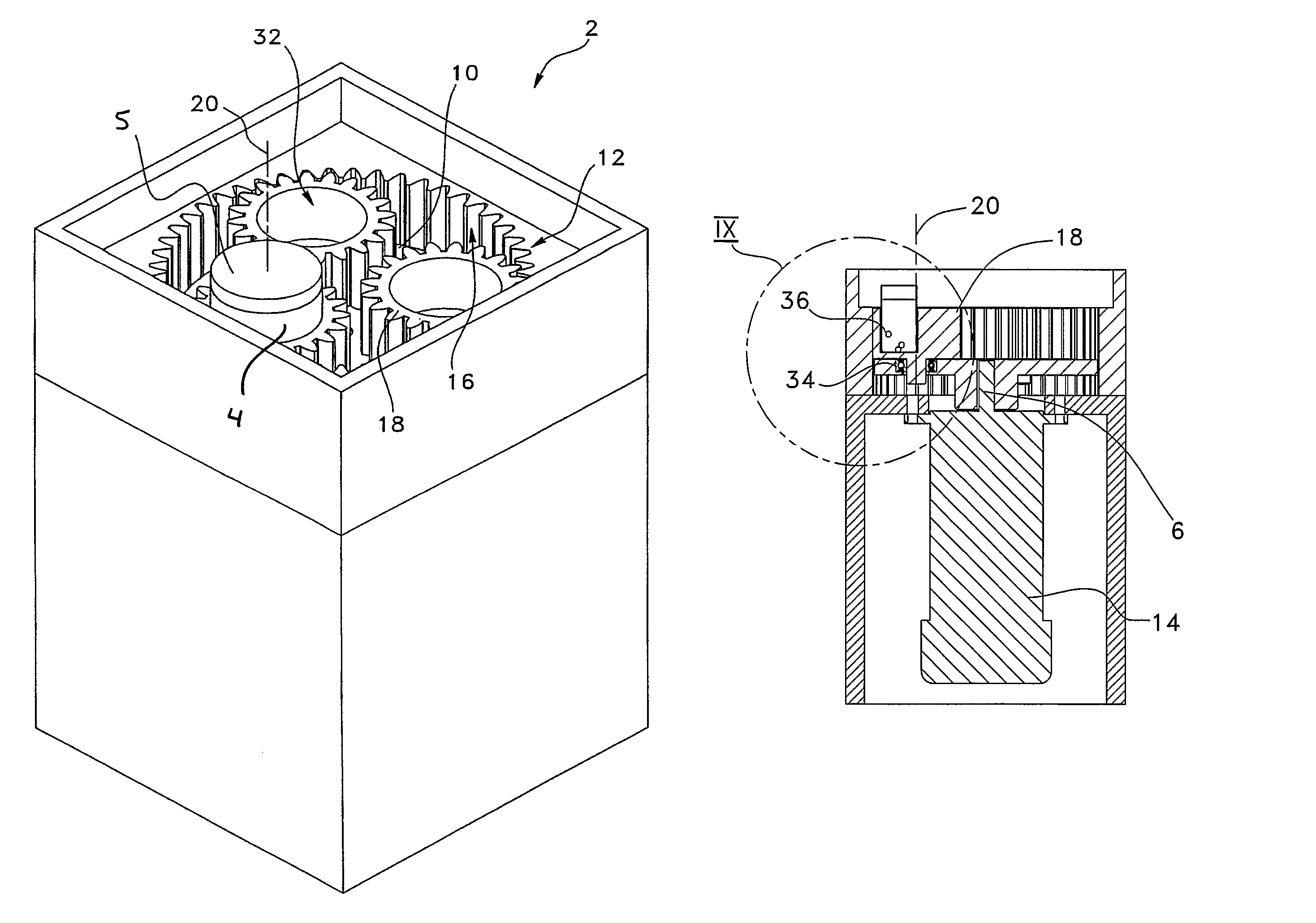
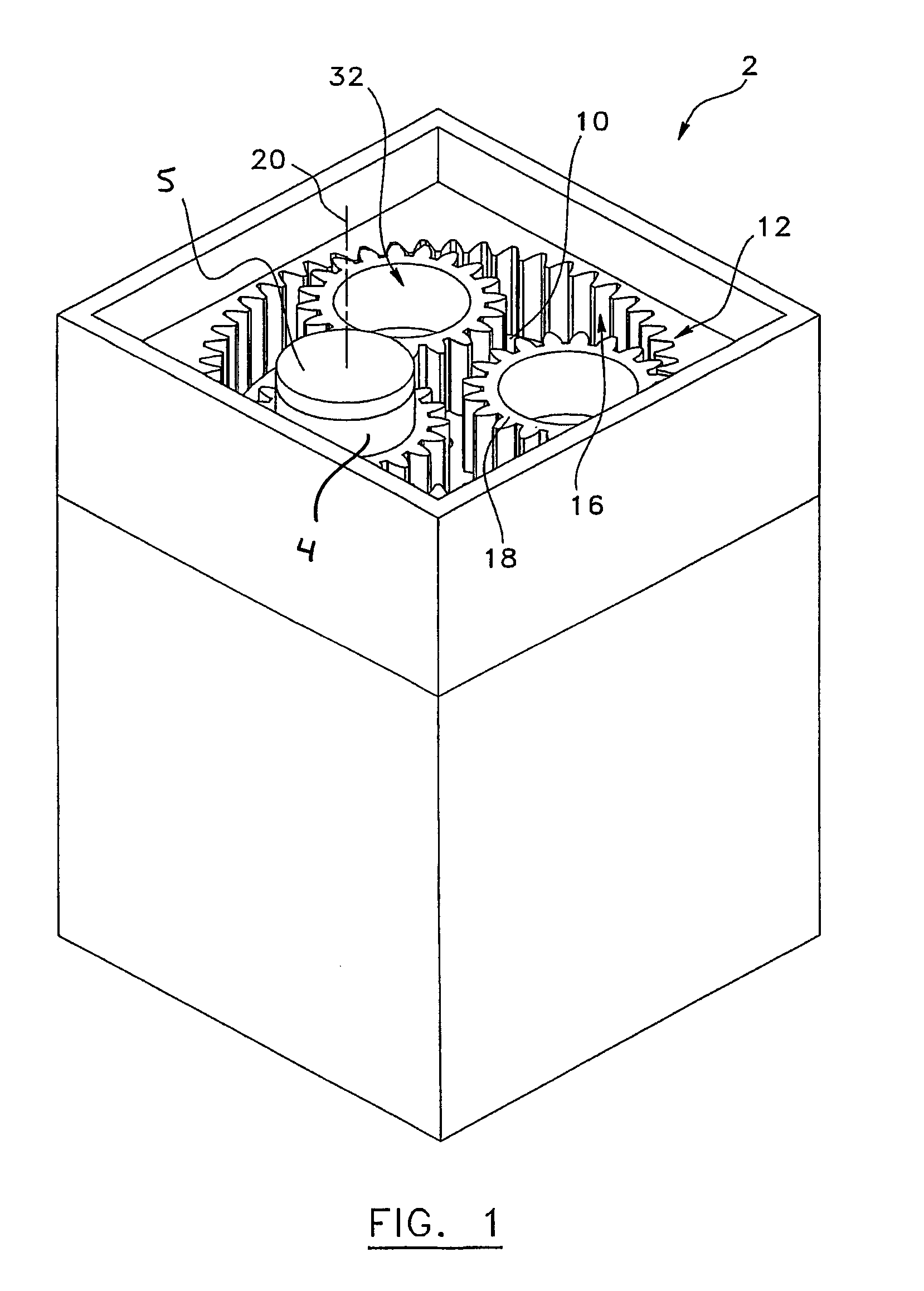
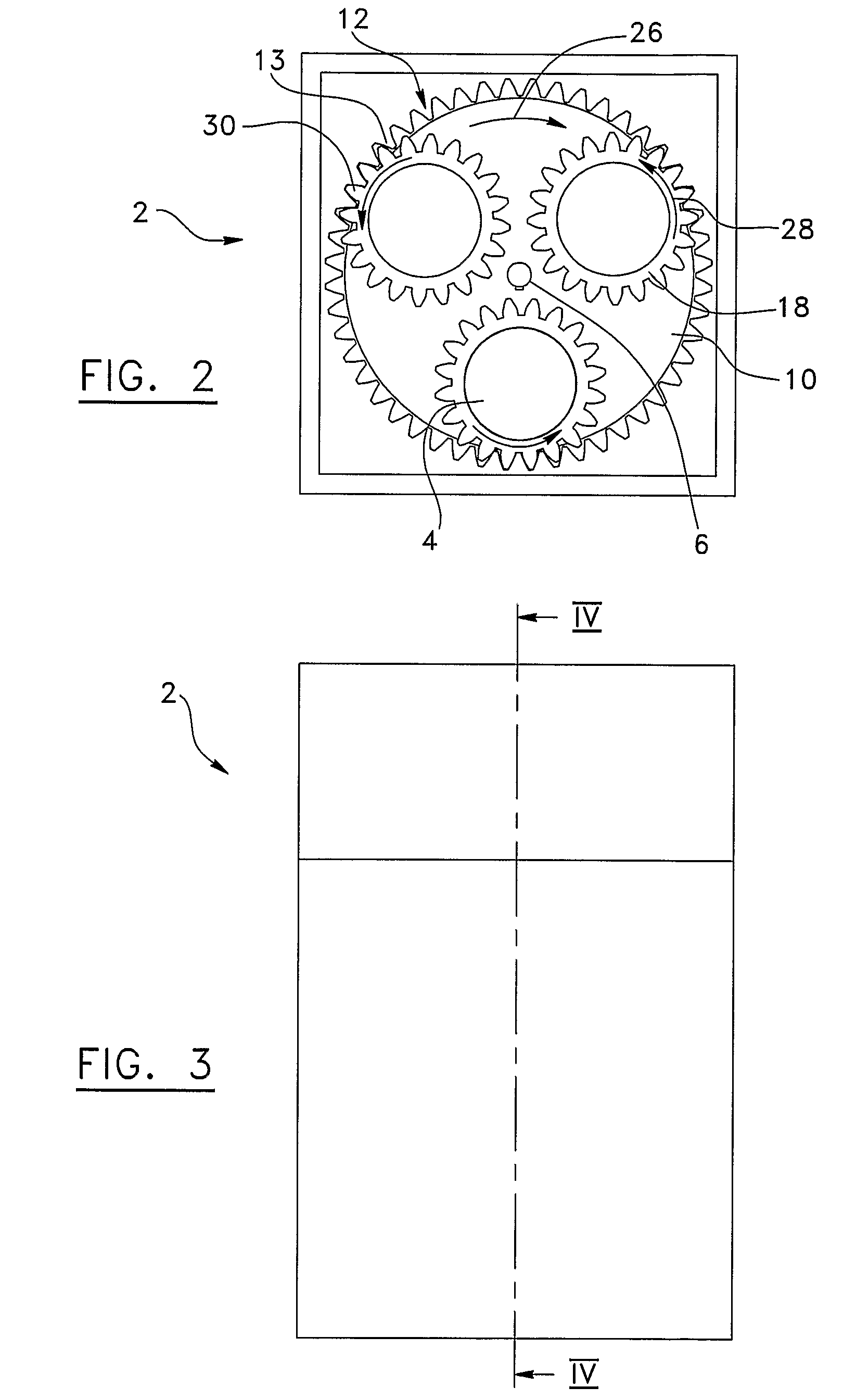
[0029]FIGS. 1 to 4 illustrate a bladeless mixer 2 according to a first preferred embodiment of the invention, which is devised to agitate and mix a compound and / or mill a product for producing powders.

[0030]The mixer 2 has a support plate 10 rotatably mounted onto a driving shaft 6 about a first axis 8 of rotation. A stationary ring gear 12 is coaxially mounted around the support plate 10 and has a portion 16 extending over the support plate 10. Preferably, the ring gear 12 has teeth 13 located on its inner surface. The support plate 10 is driven into rotation by the driving shaft 6. A motor unit 14 is operatively coupled to the driving shaft 6 in a driving engagement therewith.

[0031]The mixer 2 also has at least one pinion gear 18 rotatably mounted to the support plate 10 about a second axis 20 of rotation parallel to the first axis 8 of rotation. The pinion gear 18 has an outer surface complementary with the inner surface of the ring gear 12. The inner surface and the outer surfac...


PUM

PropertyMeasurementUnit
rotationaaaaaaaaaa
timeaaaaaaaaaa
areaaaaaaaaaaa

Abstract

A bladeless mixer / mill for agitating and mixing a compound / product. The mixer / mill comprises a driving shaft rotatable about a first vertical axis of rotation, and a motor unit operatively coupled to the driving shaft for rotating the same. A support plate is mounted onto the driving shaft and is rotatable about the first vertical axis. The mixer / mill also has a stationary ring gear coaxial to the support plate. The stationary ring gear has a portion with an inner surface extending above the support plate. At least one pinion gear is rotatably mounted onto the support plate about a second vertical axis of rotation parallel to the first vertical axis of rotation. The pinion gear has an outer surface complementary to the inner surface of the stationary ring gear. The outer surface of the pinion gear meshes with the inner surface of the stationary ring gear. The pinion gear has a cavity wherein the compound / product to be agitated and mixed / milled is inserted.

Description

FIELD OF THE INVENTION[0001]The present invention relates to a mixer, and more particularly to a mixer which can fully and uniformly mix and agitate compounds using a planetary-like motion.BACKGROUND[0002]Agitating and mixing compounds in a container is generally done with mixers having impellers producing a flow pattern within the container to achieve the desired results. These impellers are usually of the type straight-blade turbine radial flow, pitched-blade turbine mixed flow or hydrofoil impeller axial flow, depending of the flow pattern required. Dirty accumulations surrounding the work area are usually produced during the mixing process. Therefore, cleaning these mixers often require large quantity of solvents.[0003]Moreover, although these known mixers are appropriate for mixing a large range of compounds, they are not suitable for some others because the impellers may create a lot of friction on the compounds, which can result in substance damage and change.[0004]In additio...

Claims


Application Information

Patent Timeline
Patent Type & Authority Patents(United States)
IPC IPC(8): B01F9/22B02C4/08B01F29/90
CPCB01F9/10B01F9/002B01F29/321B01F29/80B02C4/08B02C4/00B01F27/00B01F29/00
Inventor VERONNEAU, GERMAIN
Owner G EXPLORE
Why Eureka
Try Eureka