Method and apparatus for controlling engine exhaust sound for vehicles

a technology for controlling engine exhaust and vehicle exhaust, which is applied in mechanical equipment, machines/engines, gas passages, etc., can solve the problems that the conventional art apparatus does not produce a powerful exhaust sound in the engine starting region, and achieves powerful sound, good acceleration sound, and reduced back pressure

Inactive Publication Date: 2008-10-09
NISSAN MOTOR CO LTD
View PDF12 Cites 19 Cited by
  • Summary
  • Abstract
  • Description
  • Claims
  • Application Information

AI Technical Summary

Benefits of technology

[0004]Recently, it has been required to reduce back pressure and vary a level of exhaust sound in an exhaust system in response to a vehicle running state. Specifically, when a vehicle engine is started, the exhaust sound would be increased to create a powerful sound to be heard by a passenger of the vehicle. When the engine is operated in an idling region and

Problems solved by technology

Therefore, the apparatus of the conventional art fails to pr

Method used


Image

  • Method and apparatus for controlling engine exhaust sound for vehicles
  • Method and apparatus for controlling engine exhaust sound for vehicles
  • Method and apparatus for controlling engine exhaust sound for vehicles

Examples


Embodiment Construction

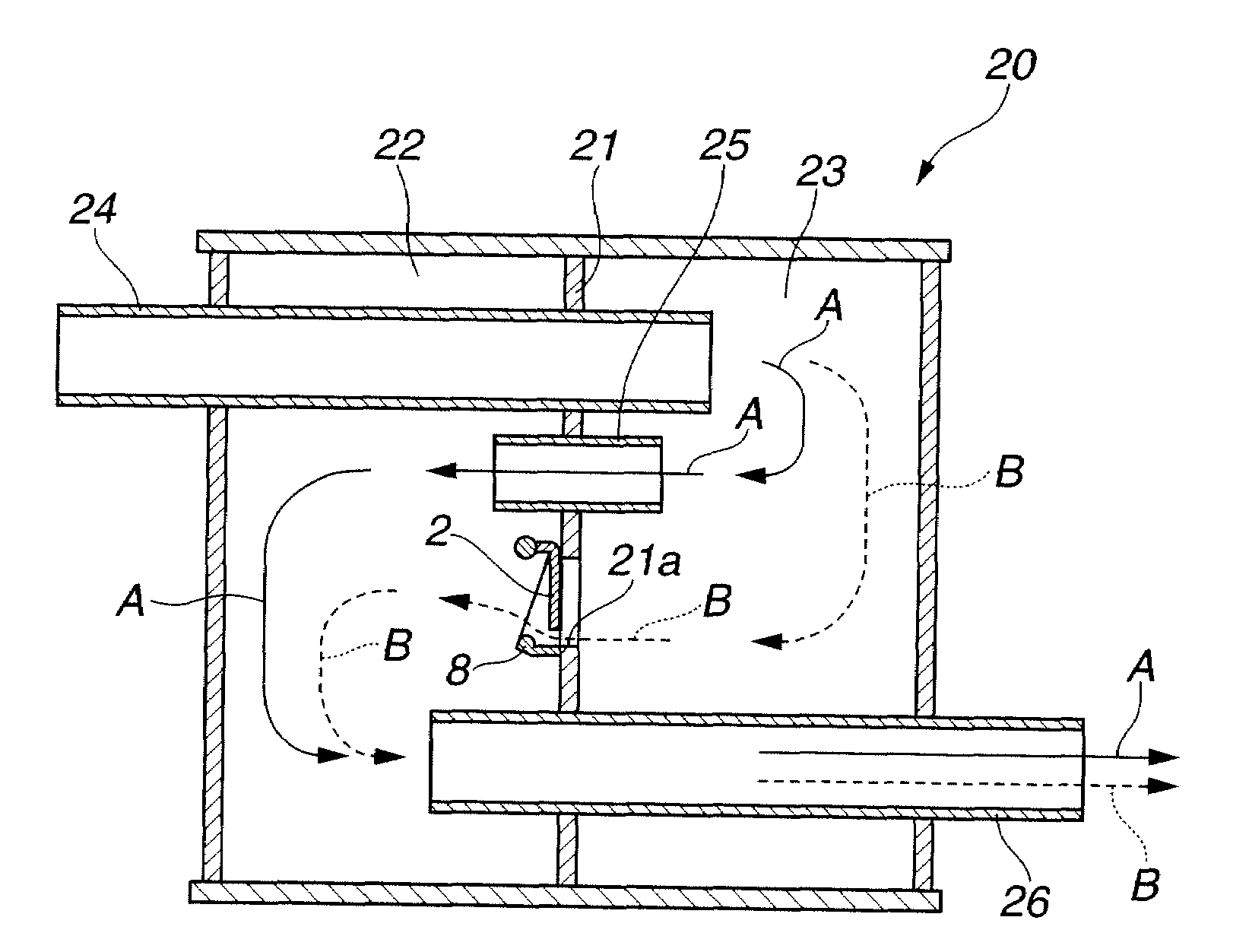
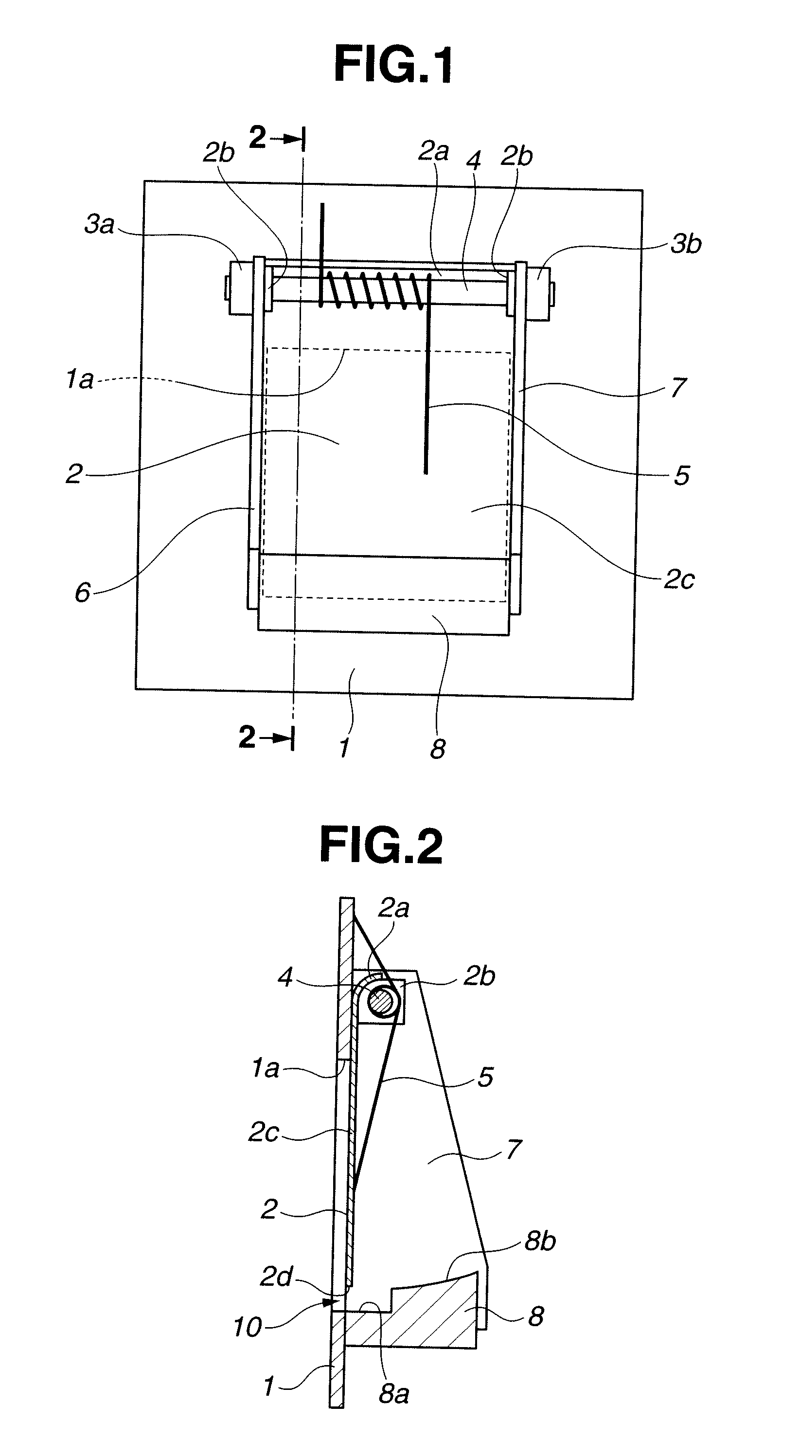
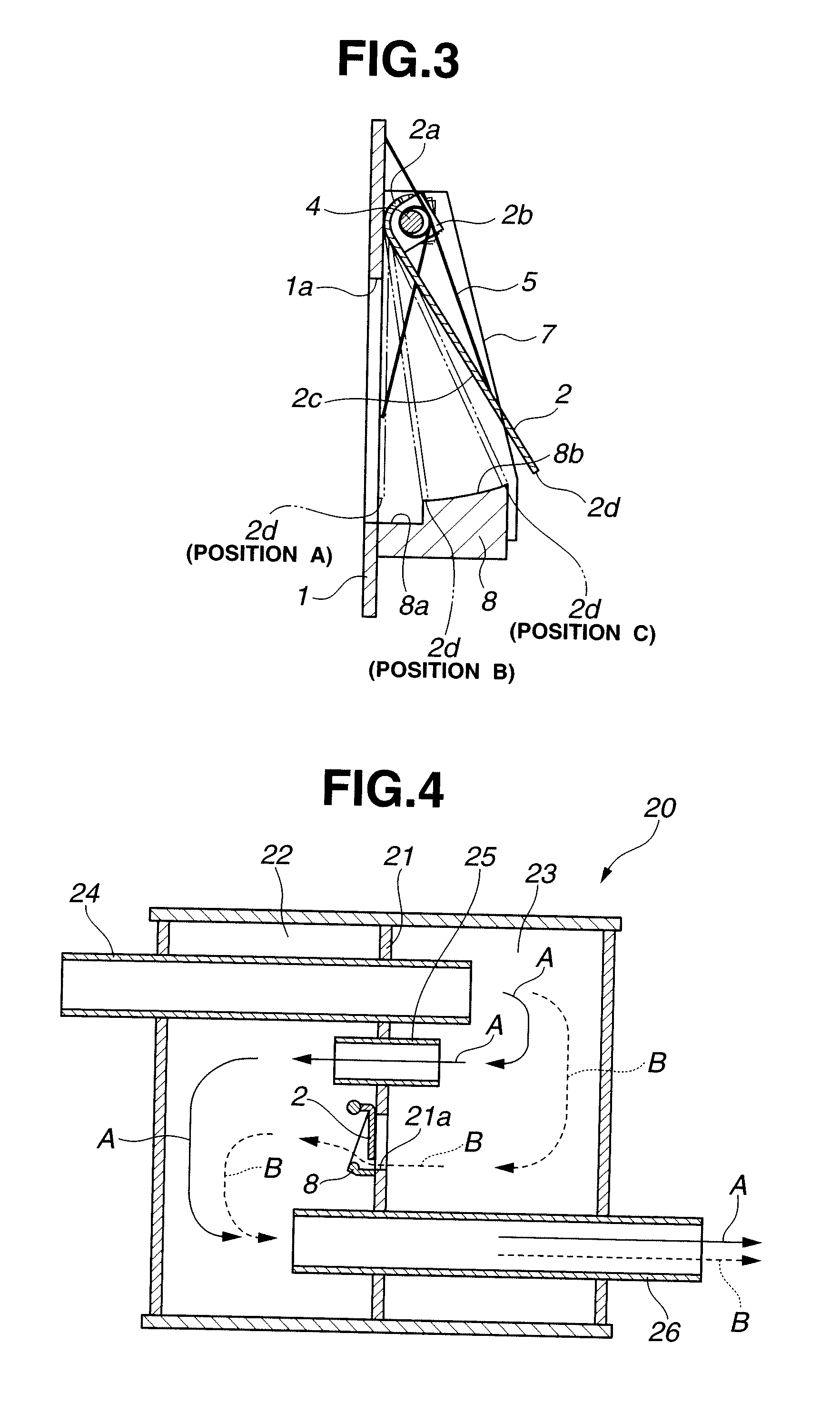
[0035]Referring to FIG. 1 to FIG. 3, an exhaust sound controlling apparatus for vehicles, according to an embodiment of the present invention, now is explained. The exhaust sound controlling apparatus includes a valve structure shown in FIG. 1 and FIG. 2. As shown in FIG. 1 and FIG. 2, the valve structure includes valve 2 that is disposed on baffle plate 1. Baffle plate 1 is disposed within a muffler as explained later which is connected to a vehicle engine. Baffle plate 1 divides an interior of the muffler into a plurality of expansion chambers which constitute an exhaust path through which a flow of exhaust gas from the engine passes. Baffle plate 1 is so arranged as to block the flow of exhaust gas in the exhaust path.

[0036]Baffle plate 1 includes a generally rectangular-shaped aperture la as shown in FIG. 1. Aperture la extends through baffle plate 1. Valve 2 is disposed on a downstream side surface of baffle plate 1 with respect to the flow of exhaust gas and so arranged as to ...


PUM


Abstract

An exhaust sound controlling method including reducing a flow rate of exhaust gas that passes through an exhaust path, to a first flow rate in accordance with increase in engine speed in a first engine speed region, and increasing the flow rate of exhaust gas to a second flow rate in accordance with increase in engine speed in a second engine speed region higher in engine speed than the first engine speed region. An exhaust sound controlling apparatus including a baffle plate and a valve that is operated to open a communication passage that communicates upstream and downstream sides of the baffle plate in an engine starting region, close the communication passage in an idling region and a low engine speed region, and open the communication passage and increase an opening of the valve as the engine speed rises in a high engine speed region.

Description

BACKGROUND OF THE INVENTION[0001]The present invention relates to method and apparatus for controlling engine exhaust sound that is emitted from an exhaust system of vehicles such as an automobile.[0002]There have been conventionally proposed engine exhaust sound controlling apparatuses for vehicles which reduce exhaust sound in high engine speed region as well as in low engine speed region while reducing exhaust loss in high engine speed region.[0003]Japanese Patent Application First Publication No. 8-109815 (corresponding to U.S. Pat. Nos. 5,614,699 and 5,739,483) indicates engine exhaust sound controlling apparatus for vehicles which includes a valve for conducting changeover of exhaust paths in response to exhaust pressure, a biasing member such as a spring which biases the valve in a closing direction of the valve against the exhaust pressure, and a spring constant changing member that reduces an increment of a reaction force of the biasing member when a rotational angle of the...

Claims


Application Information

Patent Timeline
IPC IPC(8): F01N1/00F01N13/08
CPCF01N1/084F01N1/089F01N1/166F01N1/168F01N2470/14
Inventor MAEDA, KAZUSHIGESASAKI, AKIRA
Owner NISSAN MOTOR CO LTD
Why Eureka
Try Eureka