Eureka AIR delivers breakthrough ideas for toughest innovation challenges, trusted by R&D personnel around the world.

Light-Emitting Diode Cluster Lamp

Inactive Publication Date: 2008-10-09
ENRAYTEK OPTOELECTRONICS
View PDF8 Cites 5 Cited by
  • Summary
  • Abstract
  • Description
  • Claims
  • Application Information

AI Technical Summary

Benefits of technology

[0010]The light-emitting diode cluster lamp, according to the invention, integrates the heat-conducting / emitting module with the light-emitting diode module. The heat-conducting / dissipating module is capable of dissipating the heat energy generated by the light-emitting diode module immediately to the surrounding air by using each of the at least one heat-dissipating fin, substantially increasing the heat-dissipating efficiency. Therefore, in comparison with prior art, the light-emitting diode cluster lamp, according to the invention, is more suitable for applications in lighting devices requiring highly efficient light-emitting diodes. Furthermore, the light-emitting diode cluster lamp, according to the invention, integrates many light-emitting diode lamp packages to be comparative to a point source; thus, it is capable of providing lighting with high intensity.
[0011]The light-emitting diode cluster lamp, according to the invention, can integrate a wide array of diode lamps of the current lighting devices. The casing can be designed to match the sizes of the current cylindrical or cubical batteries. Thus, the diode lamp, according to the invention, can be easily integrated with the current power source devices.

Problems solved by technology

However, after continuous light emission of a high power light-emitting diode for a period of time, the problem of overheating arises, causing the light-emitting efficiency of the light-emitting diode to drop and the brightness of the light-emitting diode not being able to increase.
The disadvantage of the lighting device, according to the lighting device shown in FIG. 1A and FIG. 1B, is that the control circuit 24 is too close to the light-emitting diodes 22.
When the light-emitting diodes 22 generate heat energy, the operation of the control circuit 24 can be easily affected and even become disrupted.

Method used


Image

  • Light-Emitting Diode Cluster Lamp
  • Light-Emitting Diode Cluster Lamp
  • Light-Emitting Diode Cluster Lamp

Examples


Embodiment Construction

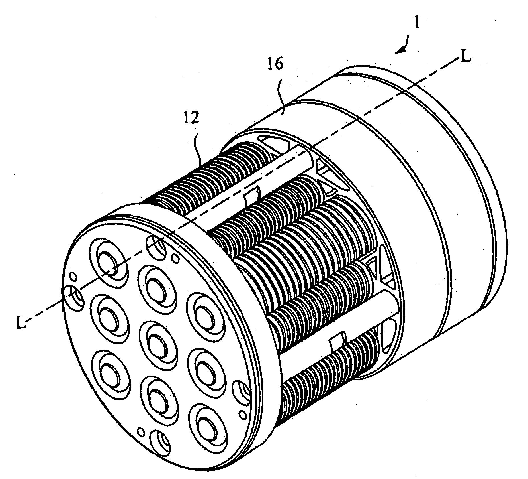
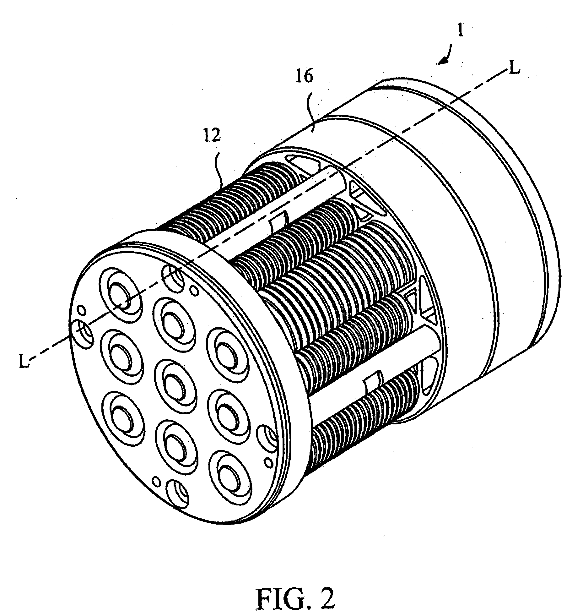
[0020]Referring to FIG. 2. and FIG. 3, FIG. 2 is an outside perspective view of the light-emitting diode cluster lamp according to the invention. FIG. 3 is a cross-section along the L-L line of the light-emitting diode cluster lamp in the FIG. 2 according to the invention. The light-emitting diode cluster lamp 1, according to the invention, includes a plurality of light-emitting diode lamp packages 12, a control circuit module 14, and a casing 16. In this embodiment of the invention, the diode lamp packages 12 are arranged into an array.

[0021]Each of the light-emitting diode lamp packages 12 includes a heat-conducting / dissipating module 122 and a light-emitting diode module 124. The heat-conducting / dissipating module 122 includes a heat-conducting device 1222 and at least one heat-dissipating fin 1224. The at least one heat-dissipating fin 1224 is mounted on a circumference of the heat-conducting device 1222 that has a flat portion. The light-emitting diode module 124 is disposed on...


PUM


Abstract

The invention relates to a light-emitting diode cluster lamp. The light-emitting diode cluster lamp includes a plurality of light-emitting diode lamp packages, a control circuit, and a casing. Each of the light-emitting diode lamp packages includes a heat-conducting / dissipating module and a light-emitting diode module. The control circuit module is used for controlling the light-emitting diode lamp packages. The casing is adapted to accommodate the light-emitting diode lamp packages and the control circuit module. When the light-emitting diode cluster lamp is connected to a power source, the control circuit module selectively makes the light-emitting diode modules emit light. The heat generated during the light emission of each of the light-emitting diode modules is conducted and dissipated by the corresponding heat-conducting / dissipating module of each of the light-emitting diode modules.

Description

BACKGROUND OF THE INVENTION[0001]1. Field of the Invention[0002]The present invention relates to a light-emitting diode cluster lamp; in particular, the light-emitting diode cluster lamp, according to the invention, is a lighting device with high intensity.[0003]2. Description of the Prior Art[0004]Because light-emitting diodes have many advantages, including power-saving, shake-resistant, rapidly-responding, and applicable to mass production, the current lighting products applying the light-emitting diodes as the light source are becoming more widely used. However, after continuous light emission of a high power light-emitting diode for a period of time, the problem of overheating arises, causing the light-emitting efficiency of the light-emitting diode to drop and the brightness of the light-emitting diode not being able to increase. Thus, different types of products applying high power light-emitting diodes all require a good heat-dissipating mechanism.[0005]Referring to FIG. 1A ...

Claims


Application Information

Patent Timeline
IPC IPC(8): F21V29/00H01L23/367H01L23/473H01L33/50
CPCF21K9/00F21Y2101/02F21V29/006F21V29/85H01L2924/0002F21V29/763H01L2924/00F21Y2115/10F21V29/51F21Y2115/30
Inventor CHEN, JEN-SHYAN
Owner ENRAYTEK OPTOELECTRONICS
Why Eureka
Eureka Blog
Learn More