Shielded surface mount connector

Inactive Publication Date: 2008-10-09
CHENG UEI PRECISION IND CO LTD
View PDF3 Cites 4 Cited by
  • Summary
  • Abstract
  • Description
  • Claims
  • Application Information

AI Technical Summary

Benefits of technology

[0008]As described above, by inserting the first and second pillars of the housing and the inserting portions and into the corresponding holes of a PCB, the connector of the present invention is mounted to the edge of the PCB, which makes the electronic products apply to the present invention much thinner. Hence, more space of the PCB is left for other designs.

Problems solved by technology

In order to meet consumers' further request, the suppliers attempt to make the electronics shorter, smaller, lighter and thinner, which challenges the technique of connector industry.
However, as the bottom of the conventional connector is mounted on the printed circuit board, the electronic products will be thicken, which is not fit the trend of the electronic development.
What's more, the conventional connector takes up much space on the printed circuit board, leaving little space for other designs.

Method used


Image

  • Shielded surface mount connector
  • Shielded surface mount connector
  • Shielded surface mount connector

Examples


Embodiment Construction

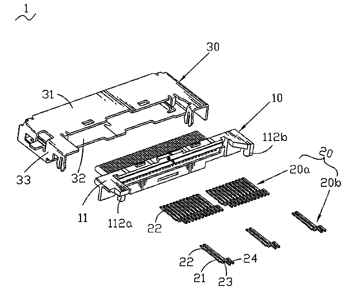
[0018]Referring to FIG. 1, a connector 1 according to the present invention includes a housing 10, a plurality of terminals 20 parallel-arranged in the housing 10 and a shelter 30 made of metal materials enclosing the housing 10.

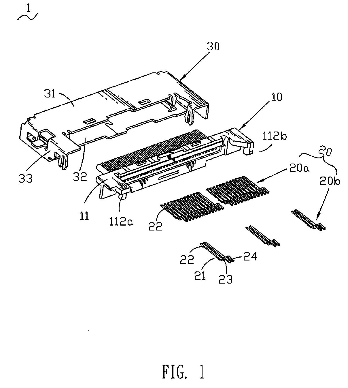
[0019]With reference to FIG. 2, the housing 10 is a one-piece structure molded of dielectric materials, which includes a transverse main body 11. Two opposite sides of the main body 11 extend forwards to form a first protruding portion 111a and a second protruding portion 111b in a same length. The front end of the first protruding portion 111a is hollowed out to form a rectangular jag 1110 at the outer corner. The inner side of the front end of the first protruding portion 111a extends downwards to form a first pillar 112a beside the jag 1110. The inner edge of the front end of the second protruding portion 111b is beveled. A second pillar 112b extends downwards from the outer side of the second protruding portion 111b. Both pillars 112a and 112b extend dow...


PUM


Abstract

A shielded surface mount connector mounted to a PCB includes a housing, a plurality of terminals and a shelter enclosing the housing. The housing provides a first protruding portion and a second protruding portion. The first and second protruding portions extend downwards respectively to form a first pillar and a second pillar. The shelter provides a first shielding portion and a second shielding portion for covering the first and second protruding portions respectively. The edges of the shielding portions extend downwards respectively to form a first inserting portion and a second inserting portion. As mentioned above, by inserting the first and second pillars and the two inserting portions into the corresponding holes of a PCB, the shielded surface mount connector is mounted to the edge of the PCB, which makes the electronic products much thinner due to the present invention, and saves more space of the PCB for other designs.

Description

BACKGROUND OF THE INVENTION[0001]1. Field of the Invention[0002]This invention generally relates to a connector and more particularly to a connector mounted to a printed circuit board.[0003]2. The Related Art[0004]Electronic products have become more and more important in people's life as the electronic industry develops rapidly. In order to meet consumers' further request, the suppliers attempt to make the electronics shorter, smaller, lighter and thinner, which challenges the technique of connector industry.[0005]When a conventional connector is assembled to a printed circuit board, it always be mounted on the surface of the printed circuit board. Correspondingly, the connector has inserting portions or fixing portions extending downwards from the bottom of the housing or shelter of the connector for mounting on the printed circuit board.[0006]However, as the bottom of the conventional connector is mounted on the printed circuit board, the electronic products will be thicken, whic...

Claims


Application Information

Patent Timeline
IPC IPC(8): H01R13/62
CPCH01R13/65802H01R12/725H01R13/6582H01R13/658
Inventor LIN, KUO-CHINLI, HUA-LIANZHU, FENGCHAO, HSIN-MIN
Owner CHENG UEI PRECISION IND CO LTD
Why Eureka
Try Eureka