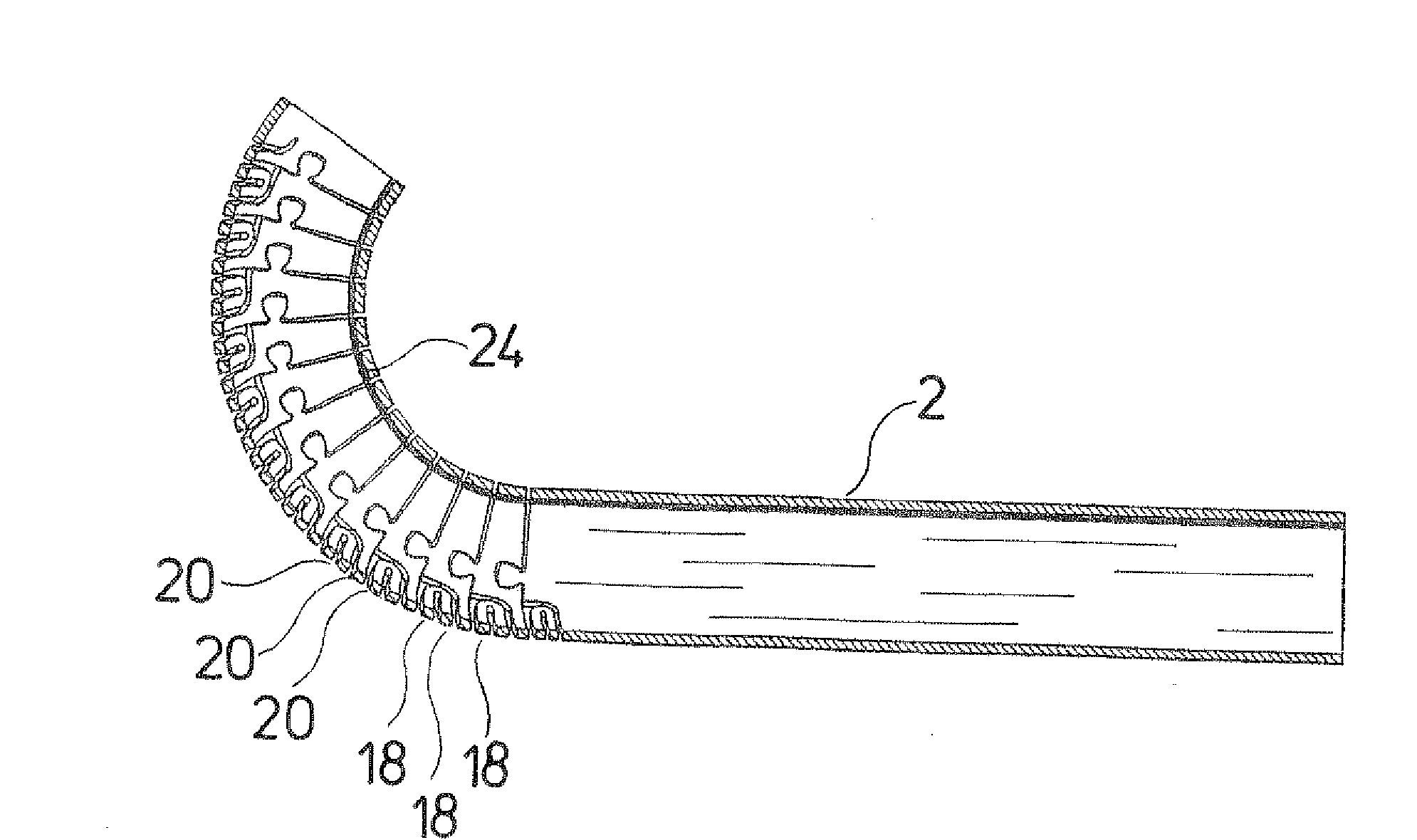
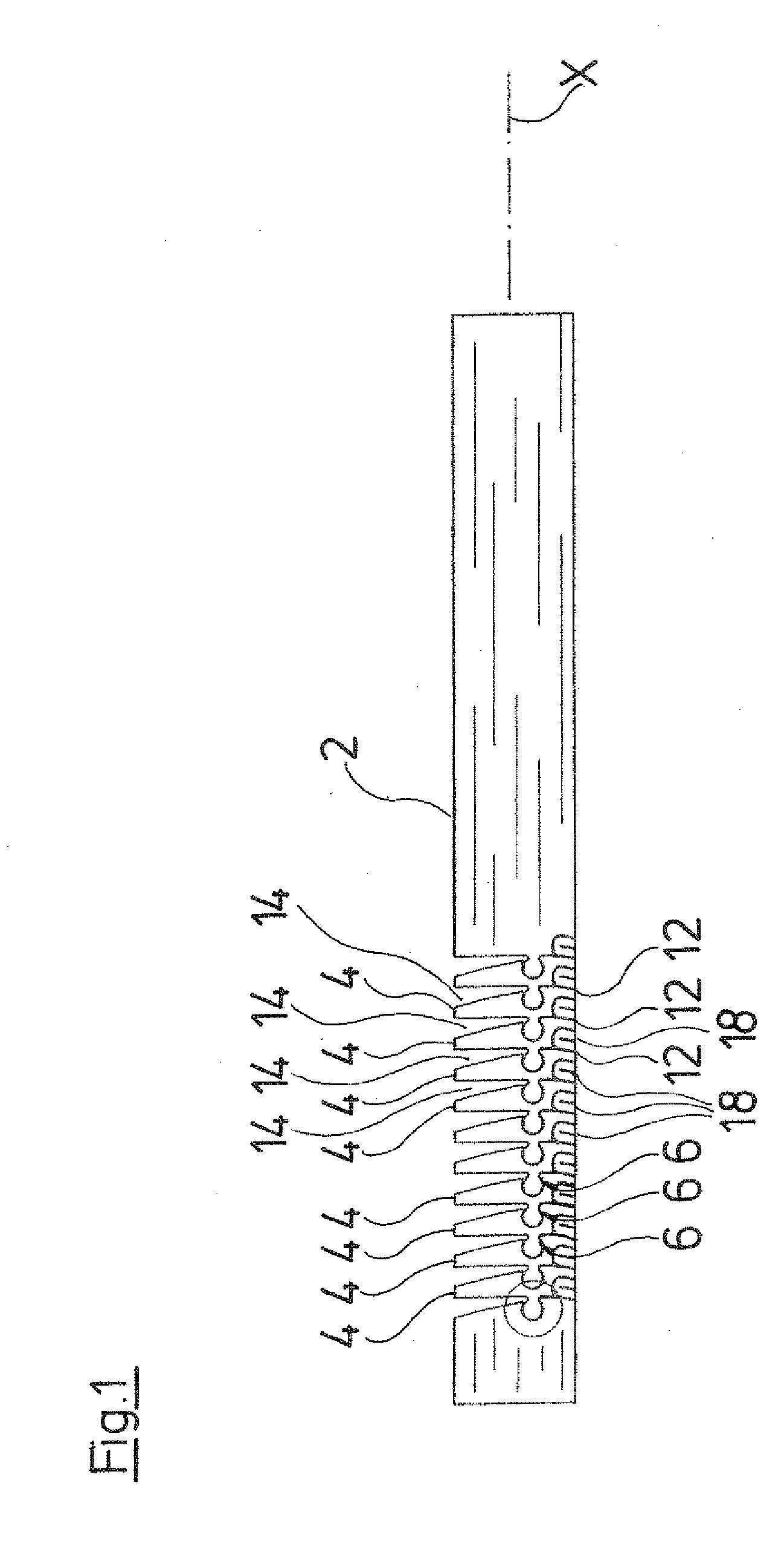
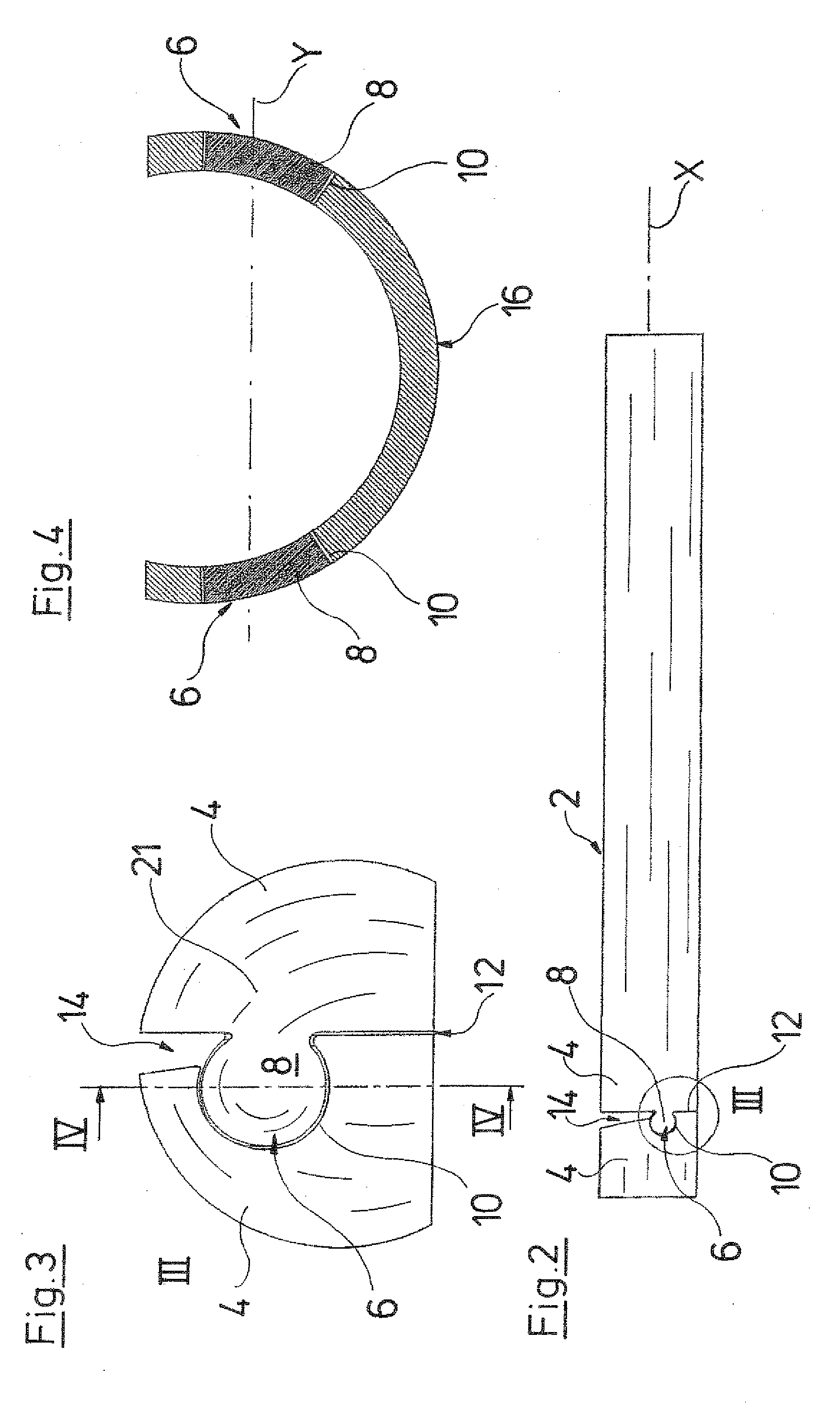
[0005]Additionally to the articulated connections, the individual tube sections are respectively connected to one another via at least one resilient connection web. The connection web or the connection webs respectively connect adjacent tube sections in a manner such that the connection web is designed in a resilient manner in the axial direction of the tube shank. The connection webs are connected to the adjacent tube sections, preferably in a physical manner, in particular with a material fit. The arrangement of the additional connection web has the
advantage that a connection of the individual tube sections is created, which is firmer compared to a purely articulated connection, and permits a greater force transmission. Simultaneously, the resilient design of the connection web ensures an adequate movability between the individual tube sections, so that a large flexibility of the tube shank is maintained.
[0007]Preferably, the connection webs are designed as one piece with the adjacent tube sections. This permits a firm connection of all tube sections, without complicated
assembly procedures becoming necessary. Moreover, the attachment of the connection web to the tube sections may be designed in a particularly slim or thin manner, so that the free lumen inside of the tube shank may be designed as large as possible.
[0014]The connection web between two adjacent tube sections preferably runs in a meandering manner with respect to its
line of action. The spring effect in the direction of the
line of action is achieved by this S-shaped or meandering design. Thereby, the spring effect is essentially not achieved by the extension of the material in the longitudinal direction, but chiefly by elastic bending in the S-design or meandering design of the connection web. The individual webs or limbs are thereby bent apart about their connection regions. With the design as a compression spring, the limbs are accordingly bent together, so that a compression of the connection web occurs. In this manner, a large
length change, in particular lengthening or extension of the connection in the axial direction of the tube shank, is achieved when deflecting the tube shank. Moreover, a large stability in the lateral direction, i.e., the radial direction is ensured.
[0015]According to a further possible embodiment of the invention, two respective resilient connection webs are arranged in diametrically opposed
peripheral regions, between two tube sections which are adjacent to one another, and these connection webs connect the tube sections to one another, wherein preferably one of the connection webs acts as a tension spring and the other as a compression spring in the direction of the longitudinal axis of the tube shank. Both connection webs are preferably arranged there such that the lines of action of their spring effect lie in the pivot plane or bending plane of the tube shank. There, the connection web acting as a tension spring is arranged on the side of the tube shank which is extended the most on bending or deflecting, while the connection web acting as a compression spring is arranged on the diametrically opposite side of the tube shank, toward which the tube shank is deflected. This is the side which is compressed the most on deflecting. Thus, the connection web acting as a compression spring is compressed on deflection, while the connection web acting as a tension spring is extended. In this manner, a larger
restoring force is produced, which moves the tube sections back again into their extended initial position, or supports such a restoring movement. Moreover, a large stability between the two tube sections, in particular in the radial direction, is achieved by the arrangement of two connection webs, so that as a whole, a larger force transmission is possible with the tube shank.
[0016]According to a further preferred embodiment, the connection webs have different spring characteristics between different pairs of tube sections which are adjacent to one another. Seen over the length of the tube shank, several or a multitude of tube sections are arranged
lying in succession, which are connected respectively to one another via at least one connection web. According to this preferred embodiment, these connection webs are not all the same, and in particular they are not designed with the same spring characteristics. Thus, one may create a tube shank which has different degrees of stiffness or flexibility characteristics over its length. Regions may be provided, which are designed stiffer than other regions. Moreover, one may thus create regions in which these are bent to a greater extent than in other regions, when deflecting or bending the tube shank. Thus, the instrument, with regard to its flexibility characteristics, may be optimally adapted to the desired application purpose.


