Printing device for printing markings onto insulated round wires

Inactive Publication Date: 2008-10-16
HANZEL ELEONORE
View PDF4 Cites 8 Cited by
  • Summary
  • Abstract
  • Description
  • Claims
  • Application Information

AI Technical Summary

Benefits of technology

[0012]An object of this invention is, therefore, a printin

Problems solved by technology

Automatic marking systems use technically complex inkjet printers using ink containing solvent for marking or printing.
However, the handling is very complex because of the mechanical adjustment of each individual stamping wheel for each individual mark.
Moreover, each stamping wheel has a fixed mark size and o

Method used


Image

  • Printing device for printing markings onto insulated round wires
  • Printing device for printing markings onto insulated round wires
  • Printing device for printing markings onto insulated round wires

Examples


Example

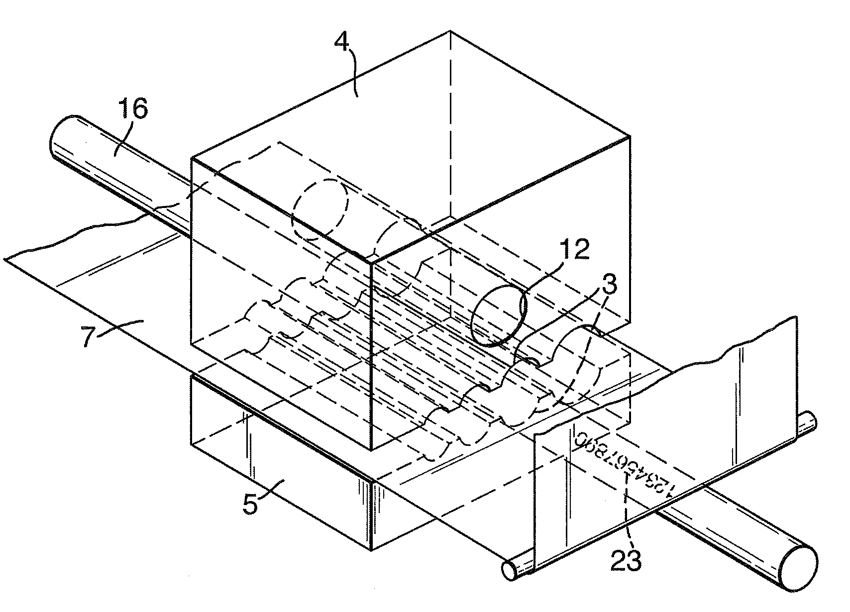
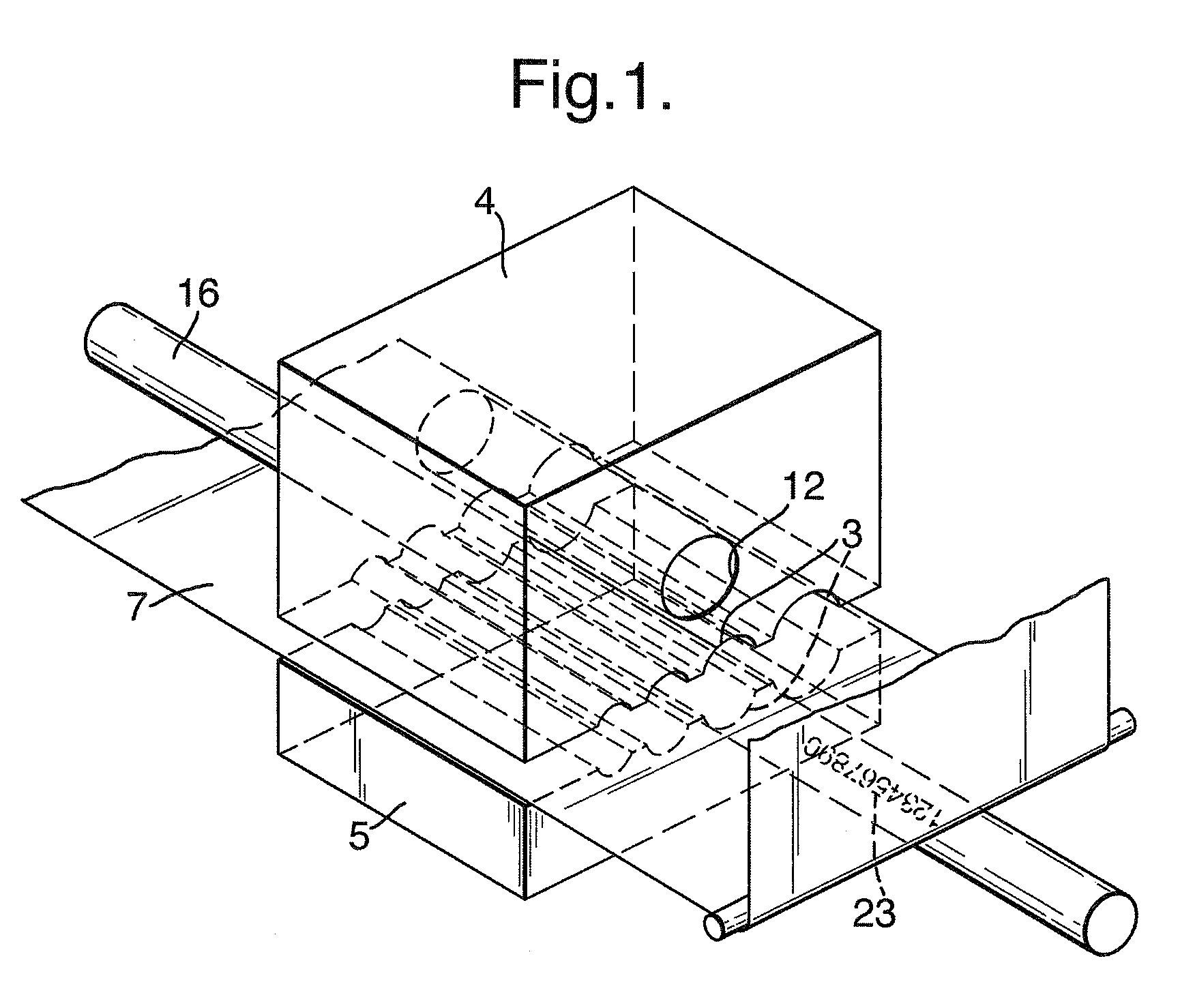
[0023]FIG. 1 shows the principle of the invention of transfer printing onto round wires. A transfer device with die halves 4) and 5), a wire 16) and the contours enclosing this of grooves 3) configured in the upper die half 4) and the lower die half 5). The approximately semicircular grooves 3) run in the same direction as the wire to be printed on inserted therein. A plurality of grooves 3) with cross-section of different sizes are arranged next to one another and preferably parallel to one another. A wire to be printed on is held in a groove adapted to size in the lower die half 4). An already printed-on transfer carrier, preferably in the form of a retransfer film 7), is guided between the two die halves 4 and 5 above the wire 16), and from said transfer carrier a marking 23) is transferred onto the wire 16) when the upper die half 4) is moved downwards and the wire 16) is enclosed by the grooves 3. A bore 12), into which a heating system is inserted, is provided in the upper die...


PUM

PropertyMeasurementUnit
Forceaaaaaaaaaa
Diameteraaaaaaaaaa

Abstract

The invention comprises a printing device for printing markings directly onto insulated round wires, comprising a printing module (1, 2) for printing the marking onto a retransfer film (7) as transfer carrier and a transport device (9, 13, 24) for the retransfer film (7) for transporting into a transfer device for transfer printing of the marking onto the round wires (16). The transfer device comprises two die halves (4, 5) with a plurality of semicircular grooves (3) for wires (16) of different diameters, wherein the lower die half (5) is configured to receive the round wires (16), the upper die half (4) is equipped with a heating means (12), and to enclose the wire (16) with the retransfer film (7) bearing the marking is movable in the direction of the lower die half (5), so that as a result of this movement the two die halves (4, 5) are joined under pressure and heat around the wire (16) to be printed on. The printing device has a commercially available connection to a keyboard-operated computer so that the markings to be printed can be created and configured simply and as required.

Description

BACKGROUND OF THE INVENTION [0001]The invention relates to a printing device for printing markings onto the covering of an insulated wire.[0002]A plurality of different wires are used as connecting elements between structural elements or assemblies in electrical and electronic control systems. These wires are generally provided with an outer insulation made of plastic material. A plurality of the wires are insulated round wires with cross-sections selected in accordance with the current density and therefore with different diameters. The insulation is configured in different colours to optically divide into corresponding groups of the set.[0003]It is additionally necessary to provide each individual wire with its own marking at both wire ends. These markings are usually defined in the design documents by the producer of the control system and enable fault-free and simple handling for production and further service. Depending on the number of control systems or devices produced, the ...

Claims


Application Information

Patent Timeline
IPC IPC(8): B41F17/00
CPCB41F16/00B41F17/10B41P2219/43
Inventor HANZEL, ELEONORE
Owner HANZEL ELEONORE
Why Eureka
Try Eureka