Laser-printable tablet, and method for manufacturing the same

Inactive Publication Date: 2017-07-13
NIPRO CORP
View PDF6 Cites 0 Cited by
  • Summary
  • Abstract
  • Description
  • Claims
  • Application Information

AI Technical Summary

Benefits of technology

[0016]The laser-printable tablet of the present invention has an outstanding effect in that it allows writing to be easily p

Problems solved by technology

Gravure offset printing and inkjet printing are methods for printing letters and numbers on the surface of a tablet, but problems were encountered with these printing methods.
Specifically, since ink was used, there was sometimes poor printing con

Method used


Image

  • Laser-printable tablet, and method for manufacturing the same
  • Laser-printable tablet, and method for manufacturing the same
  • Laser-printable tablet, and method for manufacturing the same

Examples


Example

Examples 1 to 3

[0046]Tablets containing 10 mg of montelukast and placebo tablets were prepared as the tablets of Examples 1 to 3. Each tablet weighed 200 mg and had a rounded shape with a diameter of 8 mm, and the components listed in the “Tablet” column in Table 1 were contained. Each tablet was sprayed with the first coating agent shown in the “First Cover Layer” column in Table 1, and then sprayed with the second coating agent shown in the “Second Cover Layer” column in Table 1. After these two layers were sprayed on, they were dried to produce the laser-printable tablets of Examples 1 to 3. The percentages in parentheses in Table 1 are the weight percent of the component with respect to the total solids content of each cover layer.

TABLE 1IngredientsEx. 1Ex. 2Ex. 3TablesPlacebo Tab.Tab. containingTab. containingwithMontelukastMontelukast8 mm-Diameter,10 mg with10 mg withR-Shape8 mm-Diameter,8 mm-Diameter,R-ShapeR-ShapeFirst Cover LayerFilmHydroxypropyl-3.5mg3.75mg3.5mgcomponentme...

Example

Comparative Examples 1 to 3

[0047]Other than not forming a second cover layer on the laser-printable tablets of Examples 1 to 3 above, the laser-printable tablets of Comparative Examples 1 to 3 were produced in the same manner as in Examples 1 to 3. The numbers in Comparative Examples 1 to 3 correspond to those in Examples 1 to 3.

TABLE 2IngredientsComp. Ex. 1Comp. Ex. 2Comp. Ex. 3Tab.Placebo Tab.Tab.Tab.withcontainingcontaining8 mm-Diameter,MontelukastMontelukastR-Shape10 mg with10 mg with8 mm-Diameter,8 mm-Diameter,R-ShapeR-ShapeFirst Cover LayerFilmHydroxypropyl-3.5mg3.75mg3.5mgcomponentmethylcelluloseHydroxypropyl—0.25mg—celluloseColorTitanium(IV) oxide1.5 mg1.0 mg1.5 mgchamge-(29.8%)(19.9%)(29.8%)inducingoxideYellow ferric oxide0.021mg0.015mg0.021mgDiiron trioxide0.0045mg0.003mg0.0053mg

[0048]Printability Evaluation

Example

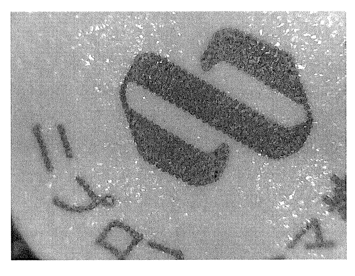
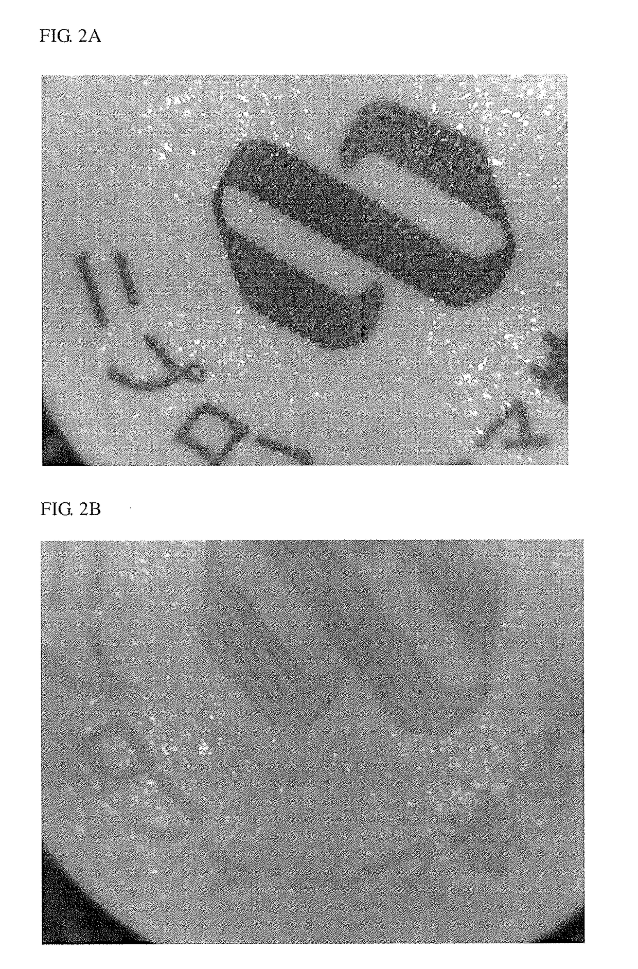
[0049]The surface of the laser-printable tablets of Example 1 and Comparative Example 1 were laser printed with a UV laser marking apparatus (model LIS-250D, made by Qualicaps Co., Ltd.) under conditions of PE=53% and 30,000 Hz. FIG. 1a is a photograph of the printing on the laser-printable tablet of Example 1, and FIG. 1b is a photograph of the printing on the laser-printable tablet of Comparative Example 1. It is clear from a comparison of the photographs in FIGS. 1a and 1b that the surface of the laser-printable tablet in Example 1 has been printed more faithfully, whereas it can be seen that the printing is fainter on the surface in Comparative Example 1. This makes it clear that providing a cover layer with a two-layer structure to the surface of the tablet affords better printing on the surface of the tablet, and this is the effect of the present invention.

[0050]Evaluation of Whether the Optically Unstable Drug Breaks Down Under UV Laser Irradiation


PUM

PropertyMeasurementUnit
Concentrationaaaaaaaaaa

Abstract

A laser-printable tablet has: a tablet containing an optically unstable drug, a first cover layer that covers the tablet and contains a first color change-inducing oxide, and a second cover layer that covers the first cover layer and contains a second color change-inducing oxide, the concentration in which the second color change-inducing oxide is contained in the second cover layer being different from the concentration in which the first color change-inducing oxide is contained in the first cover layer.

Description

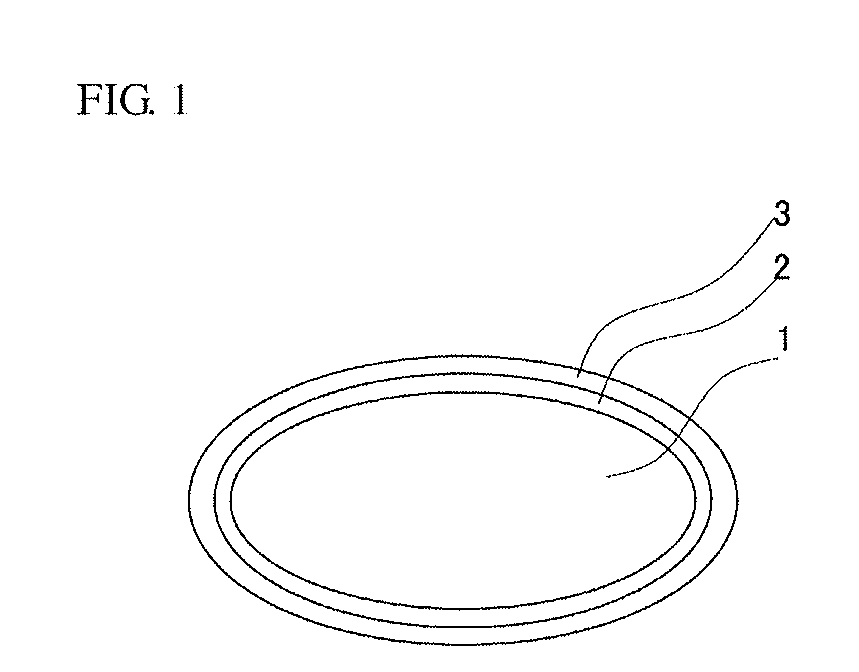
TECHNICAL FIELD[0001]The present invention relates to a laser-printable tablet and to a method for its manufacture. More precisely, it relates to a tablet that contains a drug that is optically unstable but can be laser printed, and to a method for manufacturing this tablet.BACKGROUND ART[0002]In order to reduce the risk of treatment error with tablets that are handled in a medical setting, before the tablets are provided to patients, the writing on the tablet surface is read and checked against a code table to identify the product name and so forth, confirming that the proper tablets are being given to the patients.[0003]Gravure offset printing and inkjet printing are methods for printing letters and numbers on the surface of a tablet, but problems were encountered with these printing methods. Specifically, since ink was used, there was sometimes poor printing contrast, ink that had yet to dry could rub off on other tablets, the writing could become smudged, and so forth, and in ad...

Claims


Application Information

Patent Timeline
IPC IPC(8): A61K9/20A61K9/28A61K31/47A61J3/00
CPCA61K9/2072A61J3/005A61K9/2893A61K9/2886A61K9/2813A61K9/2866A61K31/47A61J3/007A61K31/505A61K31/551A61K45/00
Inventor HOASHI, YOHEIIKUTA, SHOTARO
Owner NIPRO CORP
Why Eureka
Try Eureka