
Apparatus and method of fabricating a door

a technology of apparatus and door frame, applied in the field of doors, can solve the problems of increasing the final cost of the door frame, increasing the cost of the finished door frame, so as to minimize labor and waste, reduce the cost, and facilitate the manufacturing

Inactive Publication Date: 2008-10-16
TURNER DANIEL S
View PDF19 Cites 12 Cited by
  • Summary
  • Abstract
  • Description
  • Claims
  • Application Information

AI Technical Summary

Benefits of technology

[0012]It is a general object of the present invention to provide a door having a door light at a low cost which is easy to manufacture.
[0013]It is another general object of the present invention to minimize the labor and waste created by cutting out a door light from a door after door skins have been assembled and foam insulation has been injected into a cavity formed between the door skins.
[0014]It is yet another object of the present invention to minimize associated shipping costs for shipping a door from raw door manufacturers to finished door manufacturers by providing a door having a lower weight.

Problems solved by technology

Although the finished door does not include the above described waste material, the finished door cost does include the cost of these materials.
The uncut doors weigh more than cut doors and therefore shipping costs are also increased thereby raising the final cost to an end user.
Heretofore, tradeoffs between material waste generated during manufacture and cost were required.

Method used


Image

  • Apparatus and method of fabricating a door
  • Apparatus and method of fabricating a door
  • Apparatus and method of fabricating a door

Examples


first embodiment

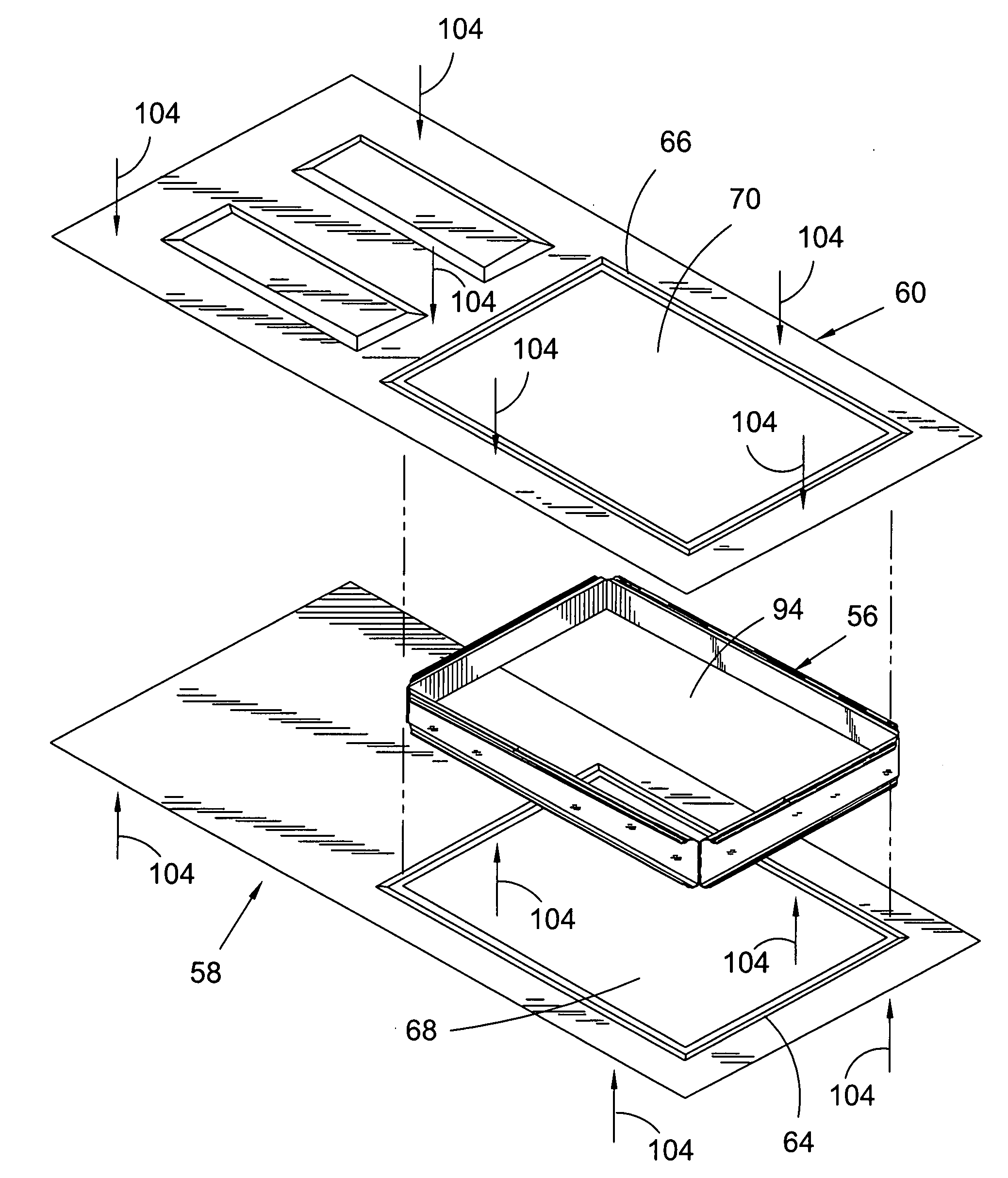
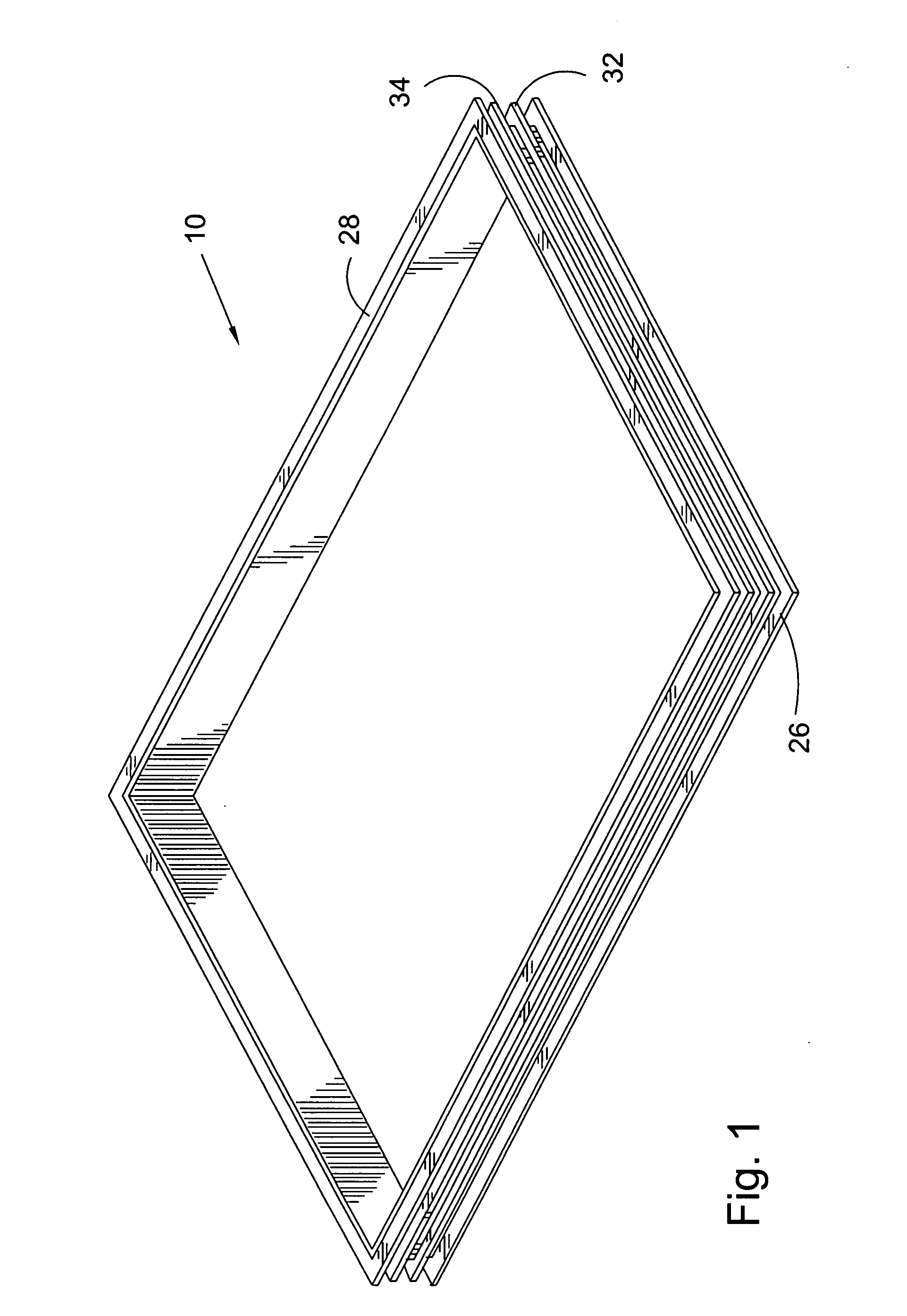
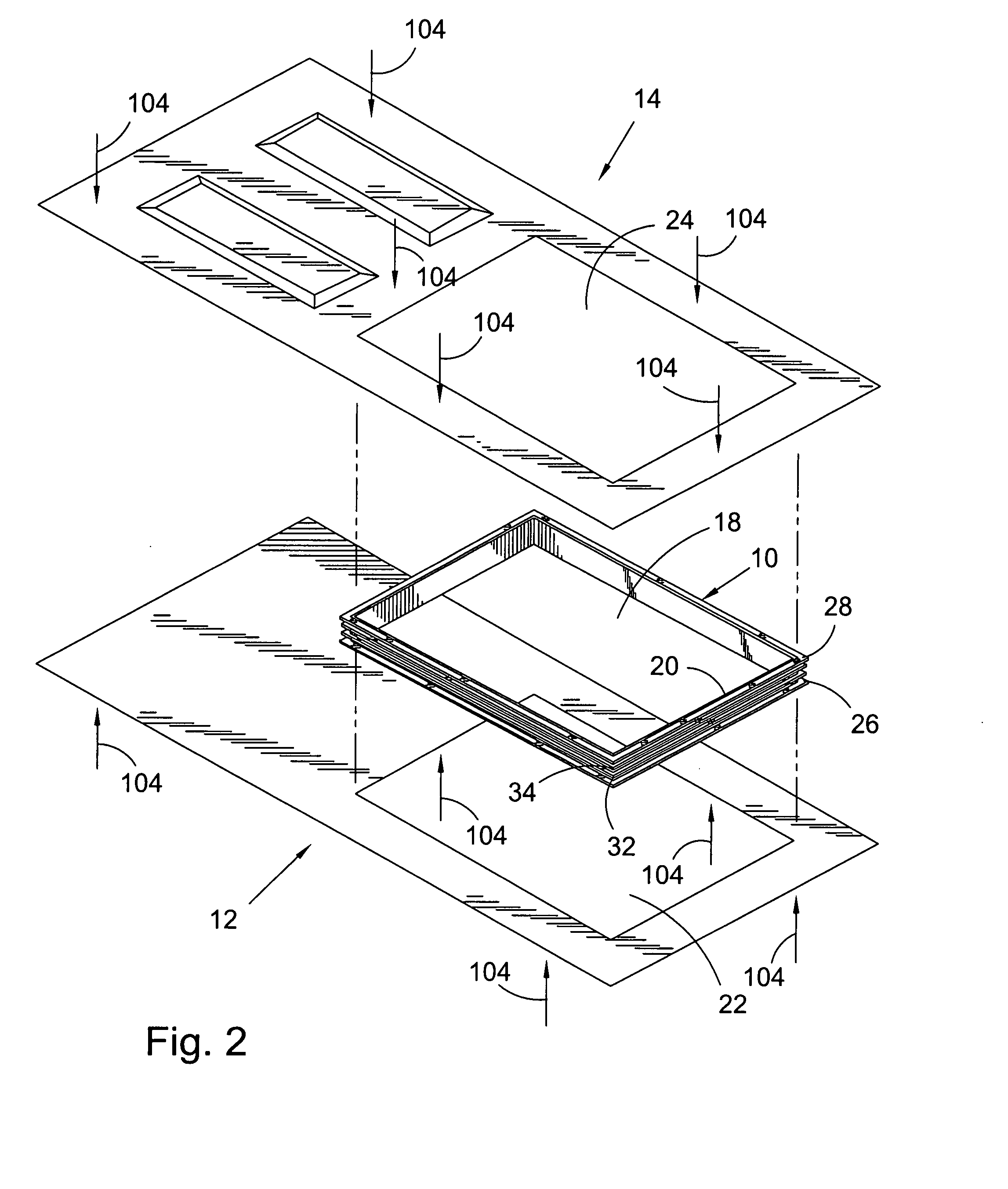
[0030]Adverting now to the figures, FIG. 1 shows a perspective view of present invention door light insert 10, while FIG. 2 shows a perspective view of door light insert 10 during installation between first and second door skins 12 and 14, respectively. FIG. 3 shows a cross sectional view of door light insert 10, FIG. 4 shows a cross sectional view of completed door 16 including door light insert 10 after fabrication and FIG. 5 shows a perspective view of completed door 16 including door light insert 10. The following discussion is best understood in view of FIGS. 1 through 5.

[0031]Door light insert 10 is used for fabrication of door light 18 in door 16. Door 16 comprises a pair of interlocking and oppositely disposed door skins 12 and 14 which, when assembled, form cavity 20 therebetween. Door skins 12 and 14 further comprise door light openings 22 and 24, respectively. During assembly of door 16, door light opening 22 is registerably aligned with opposing door light opening 24. In...

second embodiment

[0032]In some embodiments, insert 10 further comprises secondary flanges 32 and 34 positioned substantially parallel to and between engagement flanges 26 and 28. Secondary flanges 32 and 34 are substantially encapsulated in foam 30 within cavity 20 during fabrication of door 16. In some of these embodiments, secondary flanges 32 and 34 are equal in length but shorter in length than either of engagement flanges 26 or 28. In other words, secondary flanges 32 and 34 have first lengths 36, while engagement flanges 26 and 28 have second lengths 38, and first lengths 36 are less than second lengths 38. In yet other embodiments, engagement flanges 26 and 28 each comprise offset engagement surfaces 40 and 42, respectively, so that outer interfaces 44 and 46 between first and second door skins 12 and 14, respectively, and insert 10 are substantially flush. Outer interfaces 44 and 46 are created by the combination of outer surfaces 48 and 50 of door skins 12 and 14, respectively, and steps 52...


PUM

PropertyMeasurementUnit
ninety degree anglesaaaaaaaaaa
pressureaaaaaaaaaa
lengthaaaaaaaaaa

Abstract

An insert for fabrication of a door light in a door, the door includes a pair of interlocking and oppositely disposed door skins forming a cavity therebetween, each door skin includes a door light opening, the door light opening in each respective door skin is registerably aligned with the opposing door skin, the insert includes a pair of engagement flanges for engagement with the door skins within the cavity, the insert is engageable within the door light opening of each door skin to close the cavity between the door skins to prevent an infill of a foam into the door light opening during fabrication. A method for fabricating a door having a window including the steps of positioning a first door skin on a first press, positioning an insert in aligned registration with a first door light opening of the first door skin, positioning a second door skin over the insert, wherein the second door light opening is in aligned registration with the insert and the first door skin, applying pressure with the first press to secure the first and second door skins with the insert and injecting a foam into a first cavity formed between the first and second door skins and insert.

Description

FIELD OF THE INVENTION[0001]The invention broadly relates to doors, more specifically to lights for doors, and even more particularly to lights for doors constructed from complimentary door skins. The invention also broadly relates to a method of fabricating a door with a door light formed within door skins before assembly to accommodate a window. The invention also relates to an apparatus for carrying out the method of fabrication.BACKGROUND OF THE INVENTION[0002]Typically, doors constructed of steel or fiberglass comprise two molded door skins forming the front and back surfaces of the door. The door skins are joined together and filled with an expanding foam core which provides insulation, e.g., thermal and sound, and increases structural integrity. Reinforcing and mounting strips, made typically of wood, are sometimes used to provide additional structural and internal integrity when needed.[0003]Each door skin generally has rolled edges to define a perimeter edge used to secure ...

Claims


Application Information

Patent Timeline
Patent Type & Authority Applications(United States)
IPC IPC(8): B32B15/04
CPCB29C44/1233B29C44/351B29L2031/724E06B3/822E06B2003/7023
Inventor TURNER, DANIEL S.
Owner TURNER DANIEL S
Learn More