Portable housing container

Inactive Publication Date: 2008-10-16
3M INNOVATIVE PROPERTIES CO
View PDF10 Cites 0 Cited by
  • Summary
  • Abstract
  • Description
  • Claims
  • Application Information

AI Technical Summary

Benefits of technology

[0005]The present invention provides a housing container that has

Problems solved by technology

The housing container in JP1120261A, however, is not equipped with a lid, and thus, the tags are exposed by an open portion from which they are taken out.
Therefore, where the housing container is used, there is a concern that the tags m

Method used


Image

  • Portable housing container
  • Portable housing container
  • Portable housing container

Examples


Example

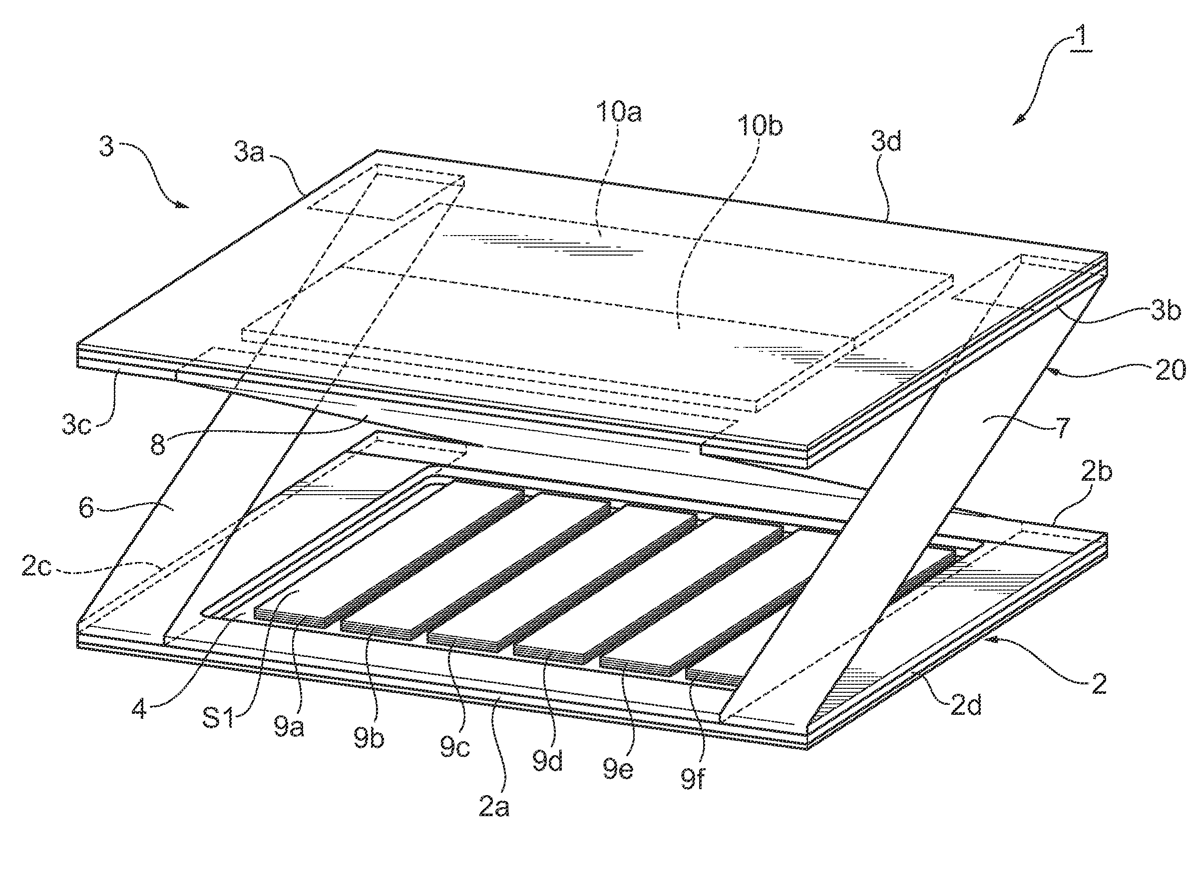
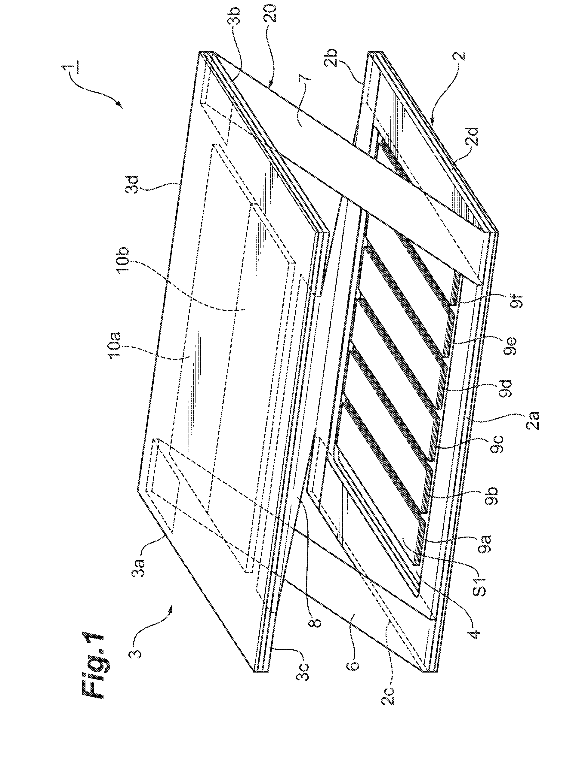
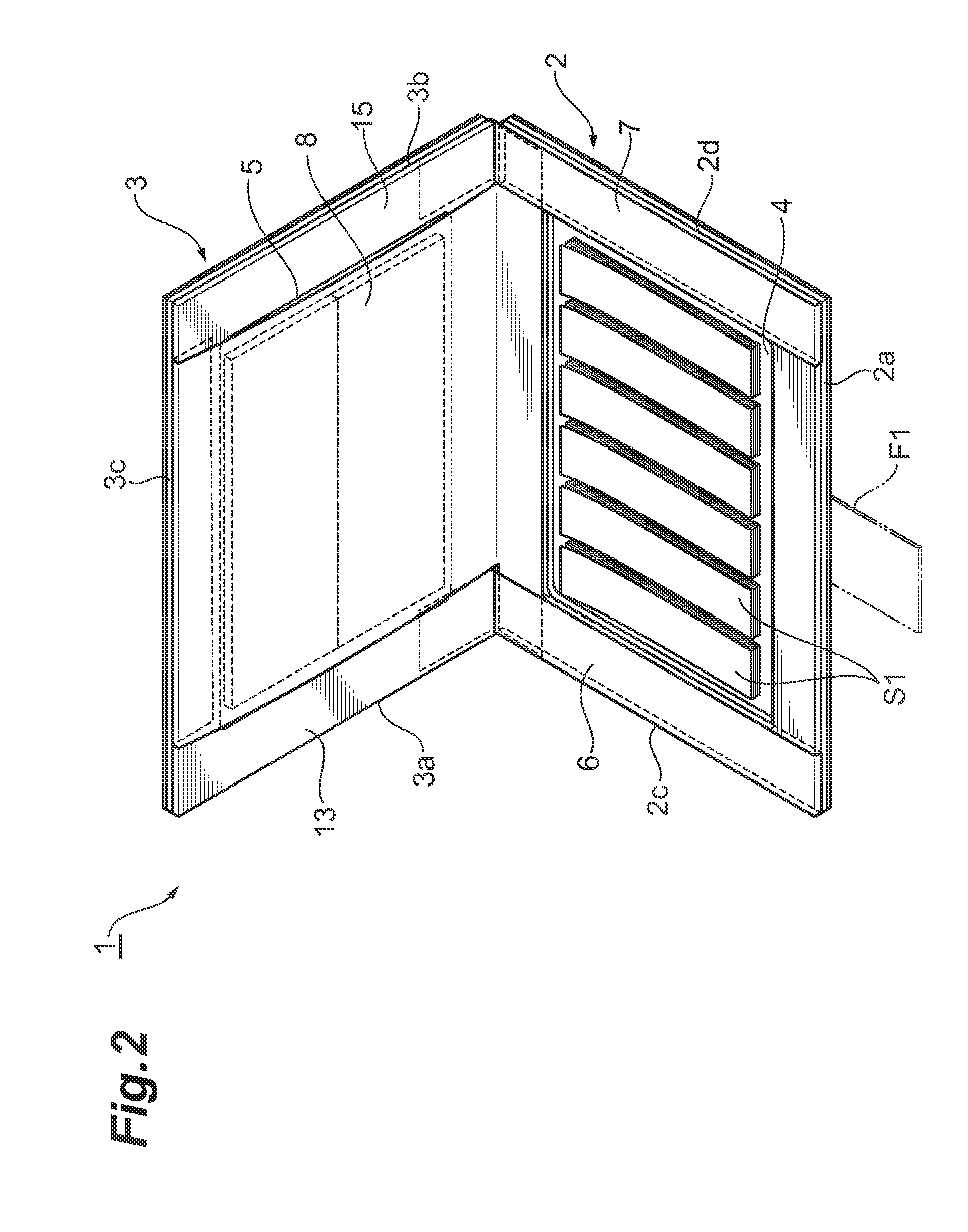
[0042]A first embodiment of a portable housing container according to the invention is illustrated in FIGS. 1-11. As shown in FIGS. 1-3, a portable housing container 1 of a front and rear side opening type has a first plate 2 and a second plate 3. In one embodiment, both plates can be made from 2 mm thick substrate, such as, but not limited to, synthetic resin or stiff paper. The geometry of the first and second plates 2, 3 is substantially rectangles. The dimensions of the first and second plates 2, 3 can be, but are not limited to, 10 cm by 7 cm. The first plate 2 includes a first housing recess 4. The second plate 3 includes a second housing recess 5. The first and second housing recesses 4, 5 have substantially similar shapes, each being a substantially rectangular opening of, for example but not limited to, 8 cm by 5.5 cm. Referring to the first and second plates 2, 3, there are no particular limitations to the widths of peripheral surfaces of the first and second housing reces...

Example

[0061]A second embodiment of a portable housing container according to the invention is illustrated in FIGS. 12-15. FIGS. 12-14 show a portable housing container 40 in accordance with the second embodiment. A first connecting member 6 and a second connecting member 7, which are provided in the housing container 40, are bridged between a first edge 42a of a first plate 42 and a fourth edge 43d of a second plate 43. Further, a third connecting member 8 is disposed between the first connecting member 6 and the second connecting member 7 and is bridged between a second edge 42b of the first plate 42 and a third edge 43c of the second plate 43.

[0062]Six stacks 9a-9f are housed within the first housing recess 44. If desired, each stack can be of different colors. A plurality of sheets S1 having adhesive applied to their rear surfaces are stacked together to form each of the stacks 9a-9f. Two stacks 10a, 10b are housed within the second housing recess 45. If desired, the stacks 10a and 10b...

Example

[0066]A third embodiment of a portable housing container according to the invention is illustrated in FIGS. 16-19. As shown in FIG. 16, an openable / closable plate assembly 60 of a portable housing container 50 in accordance with a third embodiment comprises a first frame 61 of a rectangular shape having an opening 60a, a second frame 62 of a rectangular shape having an opening 62a, a first connecting sheet 63 forming a rectangular plane, and a second connecting sheet 64 forming a rectangular frame. A first affixing section 63a and a second affixing section 63b are provided at both ends of the first connecting sheet 63. The second connecting sheet 64 is provided with a first and a second connecting members 6,7 that are parallel to each other, and with a third affixing section 64a and a fourth affixing section 64b that are parallel to each other and are bridged between the first connecting member 6 and the second connecting member 7.

[0067]The first affixing section 63a of the first co...


PUM


Abstract

The portable housing container is of the front and rear side opening type. When one side of the housing container is opened so that the first edge of the first plate may be separated from the third edge of the second plate, the first housing recess of the first plate appears and stacks of tags or memo papers housed therein can be dispensed. Similarly, when the other side of the housing container is opened so that the second edge of the first plate may be separated from the fourth edge of the second plate, the second housing recess of the second plate appears. If different types of stacked sheets are housed, respectively, in the first housing recess and the second housing recess, the different types of sheets can be carried.

Description

FIELD OF THE INVENTION[0001]The present invention relates to a portable housing container. More specifically, the present invention relates to a portable housing container useful for carrying stacks of sheets.BACKGROUND[0002]A certain housing container for small paper pieces is disclosed in Japanese Published Patent Application Hei 11-20361 (JP1120261A). The housing container as disclosed in this publication is provided with a retainer that is detachably attached to the ring of a binder for use. In the retainer made from synthetic resin by integral molding, an outer frame and an inner frame, both of which protrude from a sheet body, are formed; and the sheet body is sectioned by the outer frame and the inner frame, in cooperation, so as to construct three levels of housing compartments. Laminates of small-sized tags are housed in the first level from the top, laminates of medium-sized tags are housed in the second level, and laminates of large-sized tags are housed in the third leve...

Claims


Application Information

Patent Timeline
IPC IPC(8): B65D37/00
CPCB42D5/005B42F7/06B42P2241/02
Inventor SUGIBUCHI, TAKASHI
Owner 3M INNOVATIVE PROPERTIES CO
Why Eureka
Try Eureka