

Charge and discharge control circuit and rechargeable power supply device
- Summary
- Abstract
- Description
- Claims
- Application Information
AI Technical Summary
Benefits of technology
Problems solved by technology
Method used
Image

Examples
Embodiment Construction
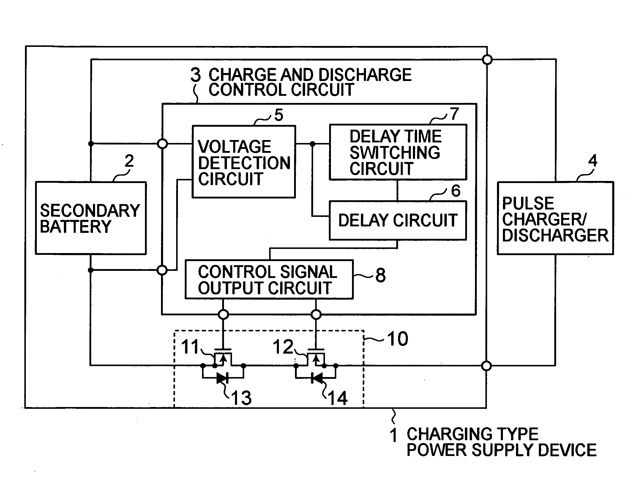
[0023]FIG. 1 is a block diagram of a charge and discharge control circuit and a rechargeable power supply device having the same built therein according to an embodiment of the present invention.
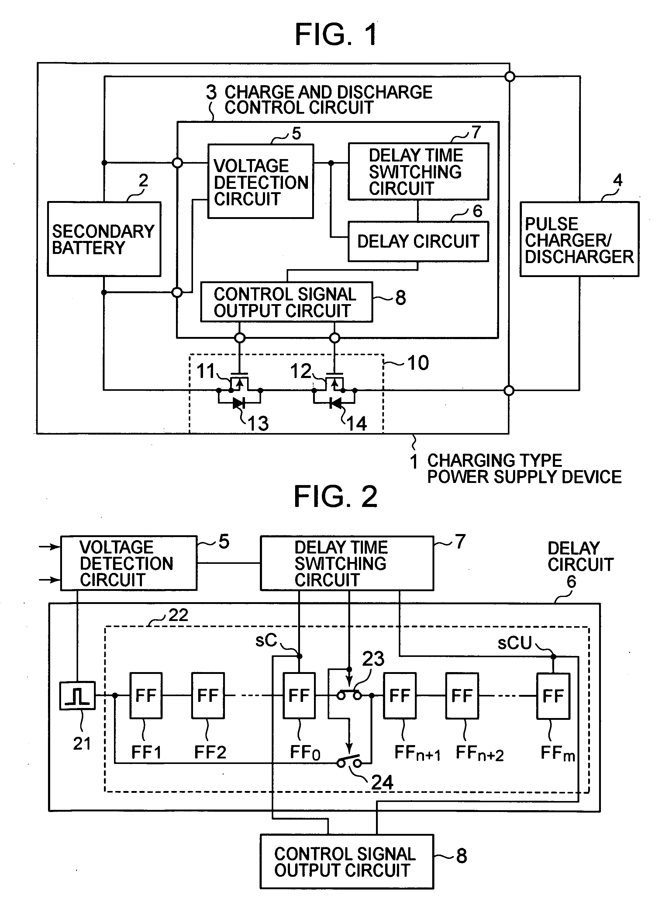
[0024]A rechargeable power supply device 1 according to this embodiment includes a secondary battery 2, a charge and discharge control circuit 3, and a charge and discharge current control circuit 10. The charge and discharge control circuit 3 includes a voltage detection circuit 5, a delay circuit 6, a delay time switching circuit 7, and a control signal output circuit 8. The charge and discharge current control circuit 10 includes a transistor 11 for discharge control and a transistor 12 for charge control.
[0025]Terminals at both ends of the secondary battery 2 are connected to voltage detection terminals of the charge and discharge control circuit 3, and the charge and discharge current control circuit 10 is connected to control signal output terminals of the charge and discharge control ...
PUM
 Abstract
Description
Claims
Application Information