Array antenna and a method of determining an antenna beam attribute

a technology of array antenna and beam attribute, which is applied in the direction of antennas, individually energized antenna arrays, electrical appliances, etc., can solve the problems of large number of sensors, prone to wear, and require calibration

Inactive Publication Date: 2008-10-16
COMMSCOPE TECH LLC
View PDF19 Cites 215 Cited by
  • Summary
  • Abstract
  • Description
  • Claims
  • Application Information

AI Technical Summary

Problems solved by technology

Such sensors may require calibration at the time of manufacture, be prone to wear and may not represent the true phase shift produced by a phase shifting network due to non-linearities of the sensor or phase shifting network.
This approach may require a large number of sensors and require complex calculations to determine the beam pattern.
It may therefore be complex and expensive to implement.

Method used


Image

  • Array antenna and a method of determining an antenna beam attribute
  • Array antenna and a method of determining an antenna beam attribute
  • Array antenna and a method of determining an antenna beam attribute

Examples


Embodiment Construction

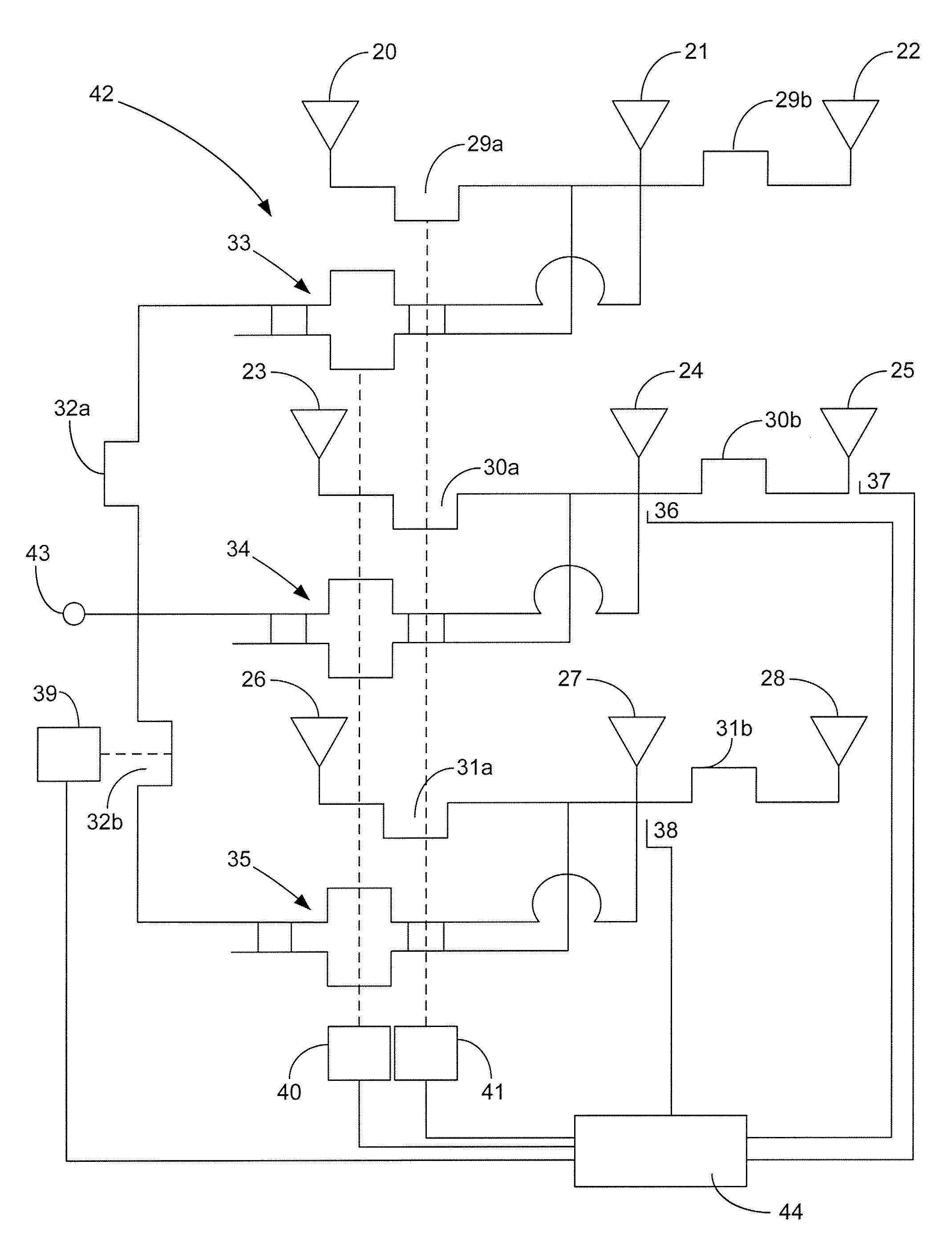
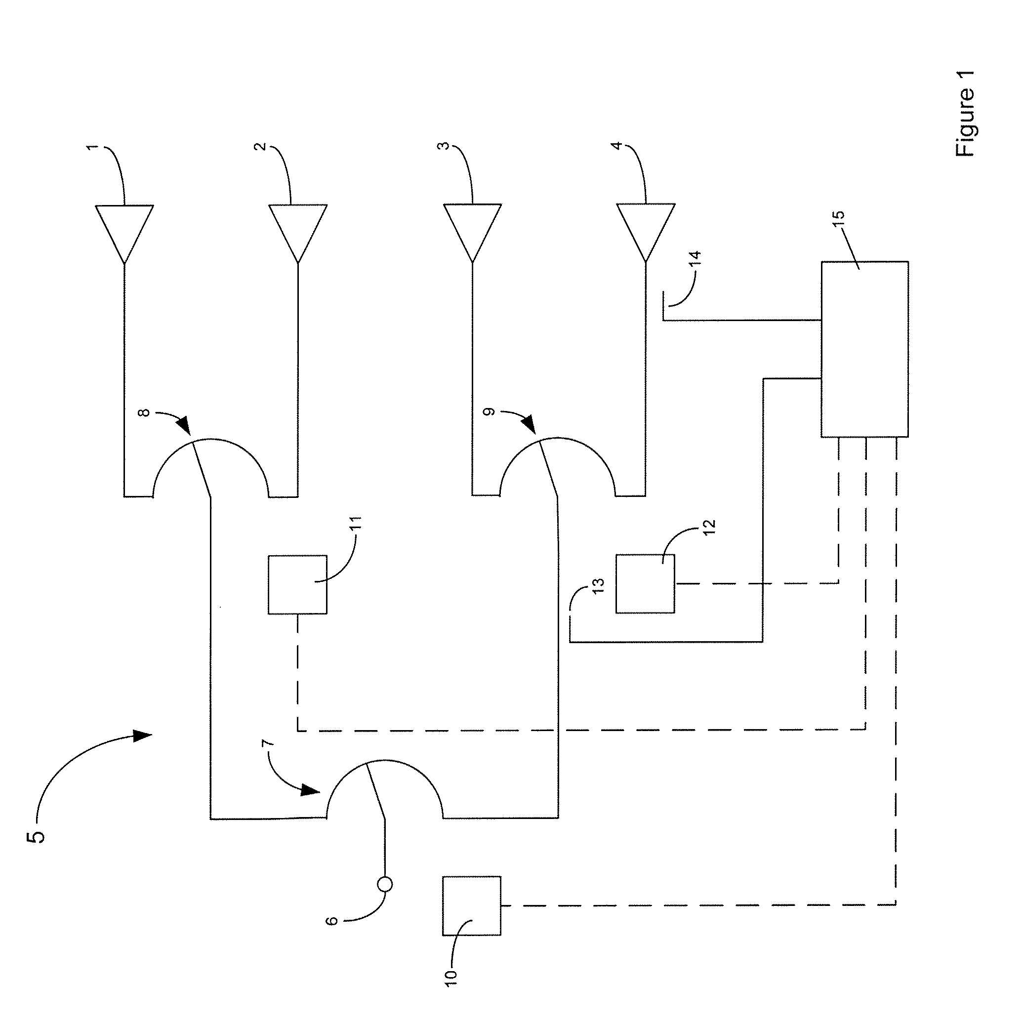
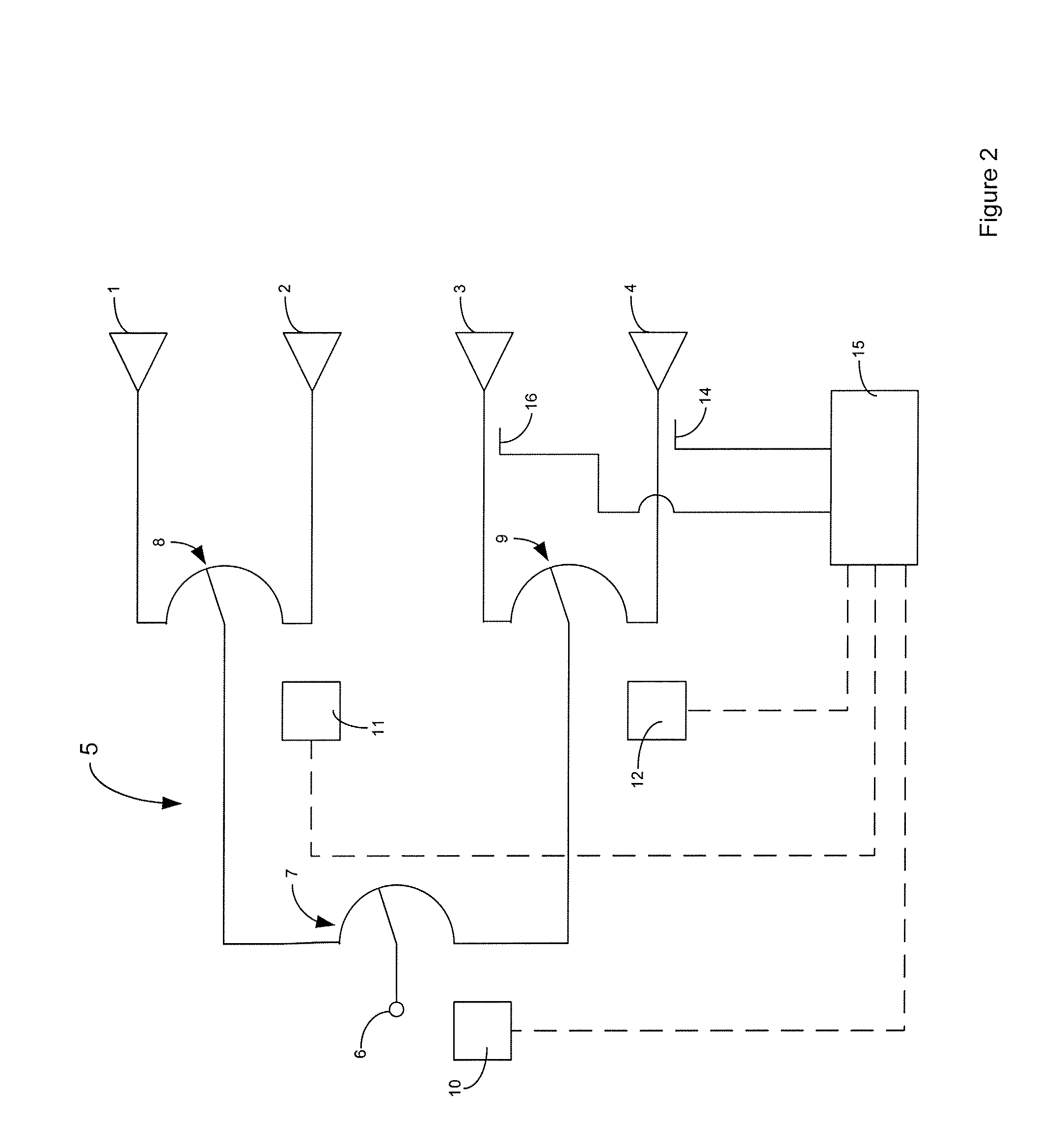
[0021]Referring to FIG. 1 an array antenna according to a first embodiment is shown schematically. Radiating elements 1 to 4 are connected via a feed network 5 to a feed point 6. In this case the feed network 5 consists of three variable elements in the form of variable differential phase shifters 7, 8 and 9. In this case the phase shifters are electromechanical passive phase shifters driven by actuators 10, 11 and 12 which may be geared motors. It will be appreciated that for symmetrically driven phase shifters a single actuator may drive all phase shifters via an appropriate mechanical linkage.

[0022]Probes 13 and 14 sense signals at the input and output of phase shifter 9 and supply the sensed signals to control circuit 15. Control circuit 15 determines the phase and amplitude difference between the signals sensed by probes 13 and 14 and based on one or both of these difference values an attribute of the beam of the antenna may be determined.

[0023]In a first method an attribute of...


PUM


Abstract

A method of determining one or more attribute of an antenna beam based on measuring phase and / or amplitude differences at different points in a feed network. By using lookup tables based on actual measurements of antenna beam attributes for phase and / or amplitude differences at different points in a feed network computation may be simplified. The method enables a relatively inexpensive control circuit to be employed while providing accurate measurement of antenna beam attributes.

Description

FIELD OF THE INVENTION[0001]This invention relates to a method of determining an antenna beam attribute by measuring at least one phase or amplitude difference between signals in a feed network sufficient to characterize an attribute of the beam of the antenna and to an array antenna incorporating a control circuit for determining an antenna attribute. The invention is particularly suited for use in cellular telecommunications systems.BACKGROUND OF THE INVENTION[0002]Telecommunication providers are increasingly incorporating antennas having remotely adjustable beam characteristics. Such antennas may include adjustable down tilt, beam width, azimuth steering or more complex beam shaping. Where such adjustment is performed electrically (i.e. by altering the electrical characteristics of the feed path) it is desirable to be able to accurately measure the beam characteristics after adjustment.[0003]Where electromechanical actuators are used the physical movement of such actuators may be...

Claims


Application Information

Patent Timeline
Patent Type & Authority Applications(United States)
IPC IPC(8): H01Q3/01H01Q21/06
CPCH01Q21/061H01Q21/08
Inventor ASBRIDGE, HAROLD E.
Owner COMMSCOPE TECH LLC
Why Eureka
Try Eureka