System, method, and apparatus for determining and using the position of wireless devices or infrastructure for wireless network enhancements

a wireless network and infrastructure technology, applied in direction finders using radio waves, instruments, wireless communication, etc., can solve the problems of not utilizing a mesh with one or more performance lookup tables associated with each vertex, limiting the technique, and conceiving a three-dimensional environment, so as to achieve certain quality of service and increase network bandwidth

Active Publication Date: 2011-09-13
EXTREME NETWORKS INC
View PDF34 Cites 142 Cited by
  • Summary
  • Abstract
  • Description
  • Claims
  • Application Information

AI Technical Summary

Benefits of technology

[0021]As the user is expected to place great value on a high degree of abstraction and simplification, the presentation of the behavior of the network will, in the preferred embodiment of the invention, be optionally available as a simple graphical plot of which areas of the deployment (e.g. which rooms in the building) will have satisfactory service, with “satisfactory” defaulted to industry norms or other desirable defaults, and configurable by the user. For example, the NMS in the current embodiment of the invention provides a simple plot of a green overlay on a floor plan of a building, where the green overlay or “fill” marks those areas of the facility where the simulated data rate provided by an 802.11g wireless network is at least 54 Mbps. Because site-specific information about the building environment is used to calculate expected network performance, the site-specific-information-enabled NMS user receives a more accurate picture of the expected network performance, a picture customized to their facility. However, it should be clear that another embodiment of the invention would have no display whatsoever, for example, in the case of a consumer appliance where the customer / user has no knowledge or interest in radio propagation or network performance characteristics.
[0092]One embodiment of the current invention includes a client that can identify its own position within the environment, and therefore knows a priori the service regions within which it is roaming. The client then knows what networks or network devices it should be able to see and what services those networks or network devices offer. Therefore, the continual scanning and updating tables of available networks is not required. Instead, the client can utilize site-specific data and knowledge of position to calculate minimum transmit power required to communicate with desirable networks or network devices and maintain a certain quality of service. This negates the need for clients to utilize maximum power levels during association, and allows clients to more intelligently regulate their transmit power levels. Furthermore, clients can utilize site-specific data and knowledge of position to more intelligently initiate handoffs. Clients can also detect if they are actually within a significant broad coverage region of a given network or network device or simply within a sliver coverage zone, in order to preferentially associate with networks and devices able to provide a consistent connection over the widest possible area

Problems solved by technology

As data communications use increases, the ability to locate the position of wireless devices that are detectable by the network has quickly become an important issue for network engineers who must design, deploy, and maintain cellular telephone systems, paging systems, wireless or wired computer networks, or new wireless systems and technologies such as personal communication networks, wireless local area networks (WLANs), ultra-wideband networks, RF ID networks, ZigBee networks, and WiFi / WiMax / mesh last-mile wireless networks.
In many cases, the wireless network interferes with itself, forcing the designer to carefully analyze many different equipment configurations in order to achieve proper performance.
Such a technique is limited by not considering other RF channel characteristics or the current network operating condition.
In addition, the technique does not utilize a mesh with one or more performance lookup tables associated with each vertex, and does not contemplate a three-dimensional environment.

Method used


Image

  • System, method, and apparatus for determining and using the position of wireless devices or infrastructure for wireless network enhancements
  • System, method, and apparatus for determining and using the position of wireless devices or infrastructure for wireless network enhancements
  • System, method, and apparatus for determining and using the position of wireless devices or infrastructure for wireless network enhancements

Examples


Embodiment Construction

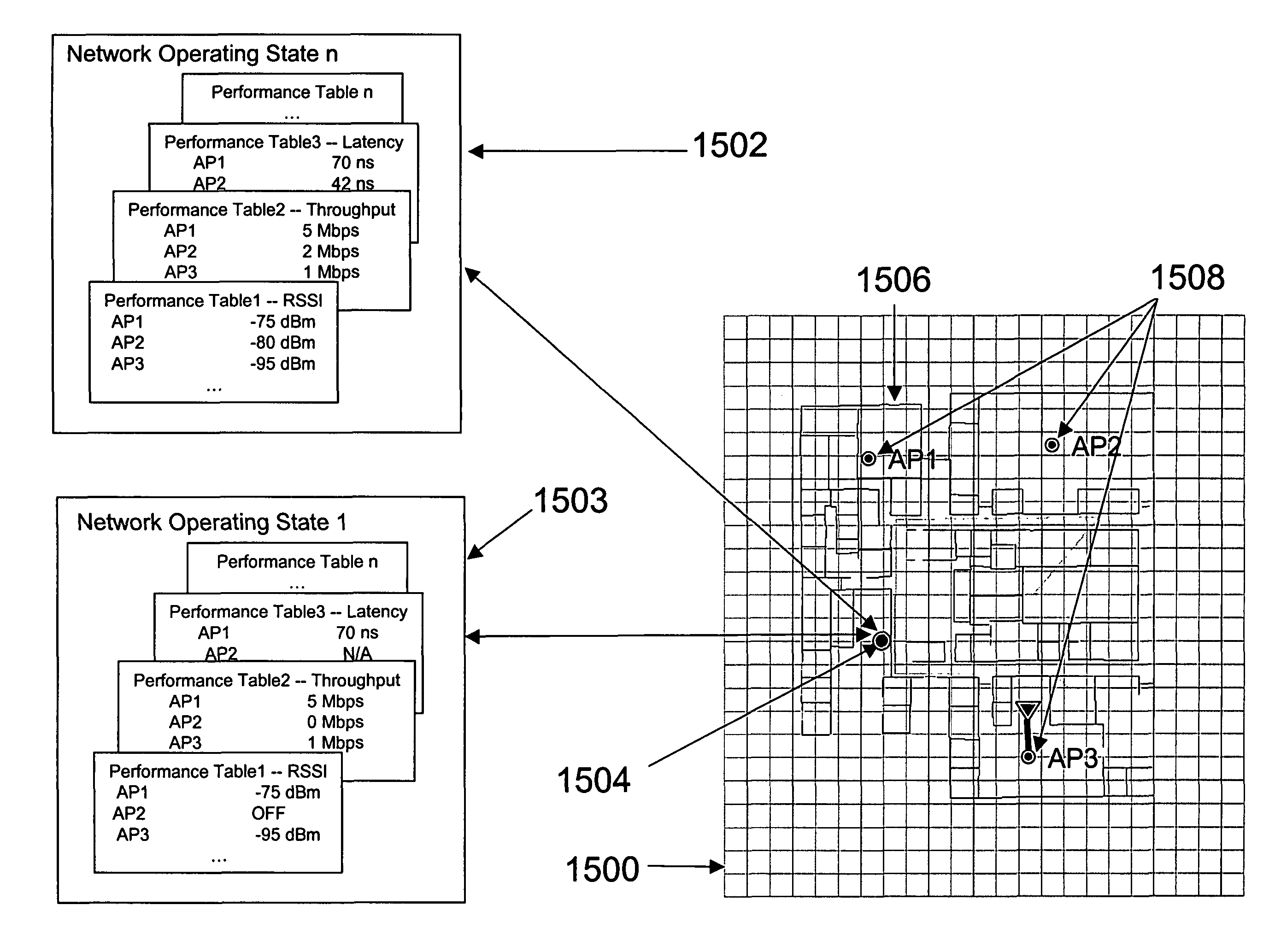
[0115]Using the present method, it is now possible to quickly and accurately determine the positions of detectable wireless devices within a known environment, and to further use position knowledge to provide enhanced capabilities for wireless and combined wired / wireless networks. The present invention is a significant advance over the prior art through its use of a novel method of using one or more performance look up tables to map RF channel characteristics into actual positions within an environmental model, and through its exploitation of this novel position estimation method to provide enhanced quality of service, power management, security, and interference detection and mitigation, and autonomous or adaptive network configuration in wireless networks.

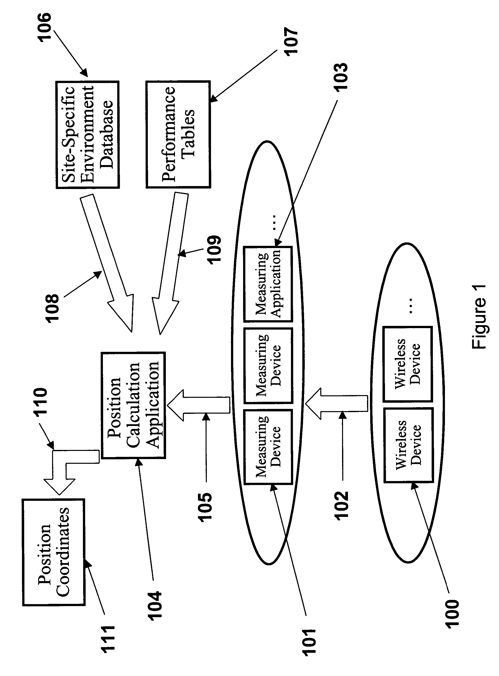
[0116]Referring now to FIG. 1, there is depicted the logical representation of a wireless communication network as it relates to the present invention. In FIG. 1, one or more wireless devices 100 exist within a wireless network. ...


PUM


Abstract

A system and method for estimating the position of wireless devices within a wireless communication network combines measured RF channel characteristics for the wireless device with one or more predicted performance lookup tables, each of which correlates an RF channel characteristic to some higher order network performance metric and / or a position within an environmental model. Measured RF channel characteristics for wireless devices are compared against the performance lookup tables to determine the sent of lookup tables that most closely match the measured RF channel characteristics. The positions within the environmental model corresponding to the selected set of matching lookup tables are identified as possible locations for the wireless device. The performance lookup tables are uniquely constructed by site-specific location, technology, wireless standard, and equipment types, and / or the current operating state of the communications network.

Description

CROSS-REFERENCE TO RELATED APPLICATIONS[0001]The present application is related to the following U.S. Patents: U.S. Pat. No. 6,317,599; U.S. Pat. No. 6,442,507; U.S. Pat. No. 6,493,679; U.S. Pat. No. 6,499,006; U.S. Pat. No. 6,625,454; U.S. Pat. No. 6,721,769; U.S. Pat. No. 6,850,946; U.S. Pat. No. 6,876,951; pending U.S. patent application Ser. No. 10 / 714,929 entitled “System and Method for Automated Placement or Configuration of Equipment for Obtaining Desired Network Performance Objectives and for Security, RF Tags, and Bandwidth Provisioning;” and pending U.S. patent application Ser. No. 10 / 830,446 (2004 / 0259555) entitled “System and Method for Predicting Network Performance and Position Location Using Multiple Table Lookups”. The complete contents of these patents and applications are herein incorporated by reference. The application claims priority to U.S. Provisional Patent Application Ser. No. 60 / 590,518 entitled “Wireless Network Management System” filed Jul. 23, 2004, and ...

Claims


Application Information

Patent Timeline
Patent Type & Authority Patents(United States)
IPC IPC(8): H04W24/00H04W64/00
CPCG01S5/0252H04W64/00G01S5/02521H04L12/28
Inventor RAPPAPORT, THEODORE S.SKIDMORE, ROGER R.ANANTHA, VEERARAGHAVANREIFSNIDER, ERIC
Owner EXTREME NETWORKS INC
Why Eureka
Try Eureka