Ink jet printing apparatus and ink jet priting method

a printing apparatus and ink jet technology, applied in the field can solve the problems of ink jet printing apparatus that requires only low running costs, ink path, ink path, ink path, etc., and achieve the effect of preventing possible stripe-like density unevenness in the join

Inactive Publication Date: 2008-10-16
CANON KK
View PDF12 Cites 35 Cited by
  • Summary
  • Abstract
  • Description
  • Claims
  • Application Information

AI Technical Summary

Benefits of technology

[0024]An object of the present invention is to provide an ink jet printing apparatus and an ink jet printing method which can prevent possible stripe-like density unevenness in a joint in a print head constructed by joining a plurality of chips together even if the print head is inclined to the regular position of the print head.
[0032]Even if the print head is inclined to the appropriate position thereof, the present invention can prevent possible stripe-like density unevenness that may occur at a joint between chips. This enables high image quality to be achieved even with what is called a joint head.

Problems solved by technology

Advantageously, ink jet printing apparatuses generate only low noise during printing because the apparatuses cause ink droplets to land on a print medium for printing.
The ink jet printing apparatus also requires only low running costs owing to its capability of printing ordinary paper and the like without any special process.
However, for the full-line printing apparatus, it is very difficult to form nozzles made up of ejection orifices, ink paths, or ejection energy generating elements, over a wide range equal to or greater than the print width of large-sized print medium without causing any defect.
It is very difficult to provide ejection energy generating elements corresponding to such a large number of ejection orifices without causing any defect, in connection with a manufacturing process.
Thus, even if such nozzles can be manufactured, efficiency percentage is low and enormous manufacturing costs are required.
However, with the joint head H, a print image is likely to be degraded in portions thereof corresponding to joints b and c of the joint head H owing to the configuration thereof.
As described above, tilted joint head may result in a white or black stripe in the area printed by joints of the print head, degrading the quality of recorded images.

Method used


Image

  • Ink jet printing apparatus and ink jet priting method
  • Ink jet printing apparatus and ink jet priting method
  • Ink jet printing apparatus and ink jet priting method

Examples


first embodiment

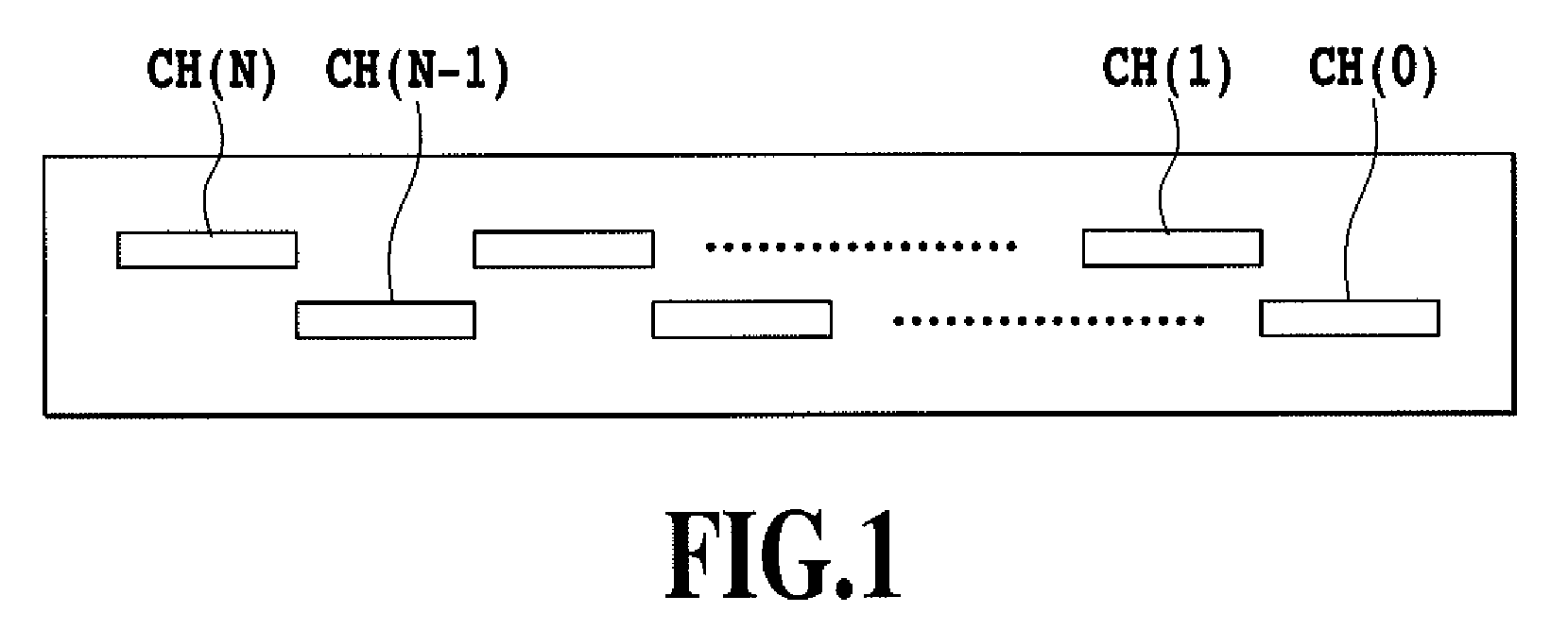
[0060]FIG. 4 is a perspective view schematically showing a full line ink jet printing apparatus (hereinafter simply referred to as a printing apparatus) in accordance with an embodiment of the present invention.

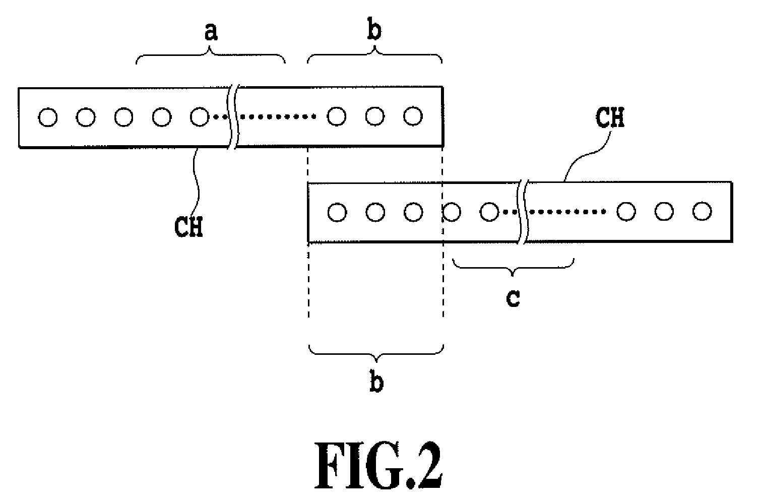
[0061]An ink jet printing apparatus 1 shown in FIG. 4 is what is called a full line type having elongate print heads (hereinafter referred to as “joint heads”) for respective ink colors each of which is constructed by joining a plurality of chips such as those shown in FIG. 1. In FIG. 4 shows that four print heads H eject four color inks, yellow (YE) ink, magenta (M) ink, cyan (C) ink, and black (Bk) ink, respectively, to form an image. However, the present invention is not limited to the types of the inks used, the number of print heads, and the like shown in FIG. 4. These factors can be optionally set and the present invention is effective in any case.

[0062]The full-line printing apparatus performs a printing operation by conveying a print medium along a direction substanti...

second embodiment

[0097]Now, a second embodiment of the present invention will be described.

[0098]The first embodiment controls the amount (ejection amount) of ink droplets ejected from the nozzles positioned in each of the joints in the print head H. In contrast, the second embodiment reduces the occurrence of white and black stripes in an area printed by the nozzles positioned in the joint by controlling the number of ink droplets ejected from the joint in accordance with the inclination of the print head H. An ink jet printing apparatus in accordance with the second embodiment is of a full-line type using what is called a joint head composed of a plurality of combined chips and having a configuration shown in FIGS. 4 to 10 as is the case with the first embodiment.

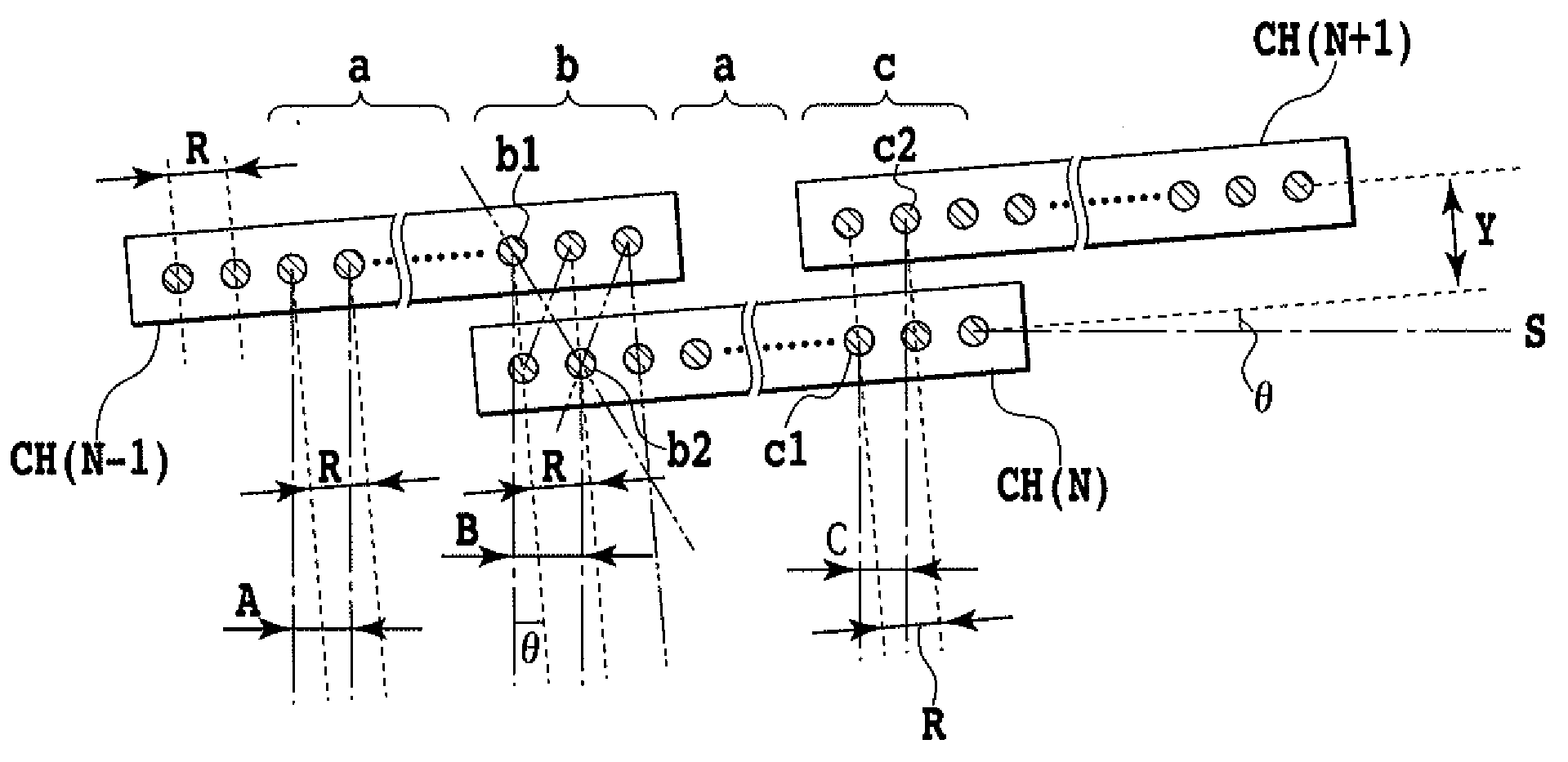
[0099]In the print head H used in the second embodiment, joined ends overlap each other as is the case with the first embodiment. FIG. 11 shows the arrangement of dots formed by the nozzles positioned in that area (joint) b of the print h...

third embodiment

[0107]In the description of the second embodiment, control is performed such that the nozzle usage rate of the nozzles positioned in each joint is uniform within the same chip by way of example. In contrast, a third embodiment of the present invention not only performs the ejection control of the joint against the inclination of the print head but also performs control such that the usage rate of the nozzles in the joint in each chip decreases consistently with the distance between the nozzles and the end of the chip as shown in FIG. 14.

[0108]In general, in the ink jet print head, the nozzles located closer to the end of the chip tend to exhibit lower ejection performance (ejection direction or amount). Thus, performing control such that the ink ejection rate is reduced for the nozzles located closer to the end of the chip is conventionally known to be effective for inhibiting possible density unevenness (for example, black and white stripes) at the joint.

[0109]Thus, in the third em...


PUM


Abstract

An object of the present invention is to provide an ink jet printing apparatus which can prevent possible stripe-like density unevenness in a joint in a print head constructed by joining a plurality of chips together even if the print head is inclined to the regular position of the print head. The present invention uses a print head having the nozzle arrays being shifted in a direction in which the nozzles are arranged, so as to have overlapping portions in a direction orthogonal to the nozzle arranging direction. The present invention controls an ink ejecting operation of the nozzles in the overlapping portions between the plurality of nozzle arrays on the basis of an angle between the nozzle array arranging direction and a direction orthogonal to the direction in which the print head moves relative to the print medium.

Description

BACKGROUND OF THE INVENTION[0001]1. Field of the Invention[0002]The present invention relates to an ink jet printing apparatus that prints an image on a print medium by ejecting ink onto the print medium through nozzles formed in a print head, and in particular, to a printing apparatus using a print head having a plurality of relatively short chips which are arranged to increase the length of the print head and in each of which nozzles are arranged.[0003]2. Description of the Related Art[0004]Advantageously, ink jet printing apparatuses generate only low noise during printing because the apparatuses cause ink droplets to land on a print medium for printing. The ink jet printing apparatus also requires only low running costs owing to its capability of printing ordinary paper and the like without any special process. Furthermore, with the ink jet printing apparatus, using a plurality of color inks enable color images to be relatively easily formed. Moreover, densely arranging nozzles ...

Claims


Application Information

Patent Timeline
Patent Type & Authority Applications(United States)
IPC IPC(8): B41J29/38B41J2/145
CPCB41J2/04505B41J2/04541B41J2/0458B41J2/04588B41J2202/20B41J2/155B41J2/2132B41J29/393B41J2/04598
Inventor WADA, SATOSHIYAMAGUCHI, HIROMITSUAKAHIRA, MAKOTO
Owner CANON KK
Why Eureka
Try Eureka