This helps you quickly interpret patents by identifying the three key elements:
Problems solved by technology
Method used
Benefits of technology
Benefits of technology
[0034]According to the present invention, the circuit capable of delaying the print timing is provided for each of the LED heads of the separation type LED head. The printing position of each of the LED heads is adjusted according to the change of the exposure cycle of the separation type LED head. Therefore, even in the case of the LED printer using the separation type LED head, an effect is obtained in which the print length in each of the front end region and the rear end region of the sheet can be corrected to perform high-precision printing.
Problems solved by technology
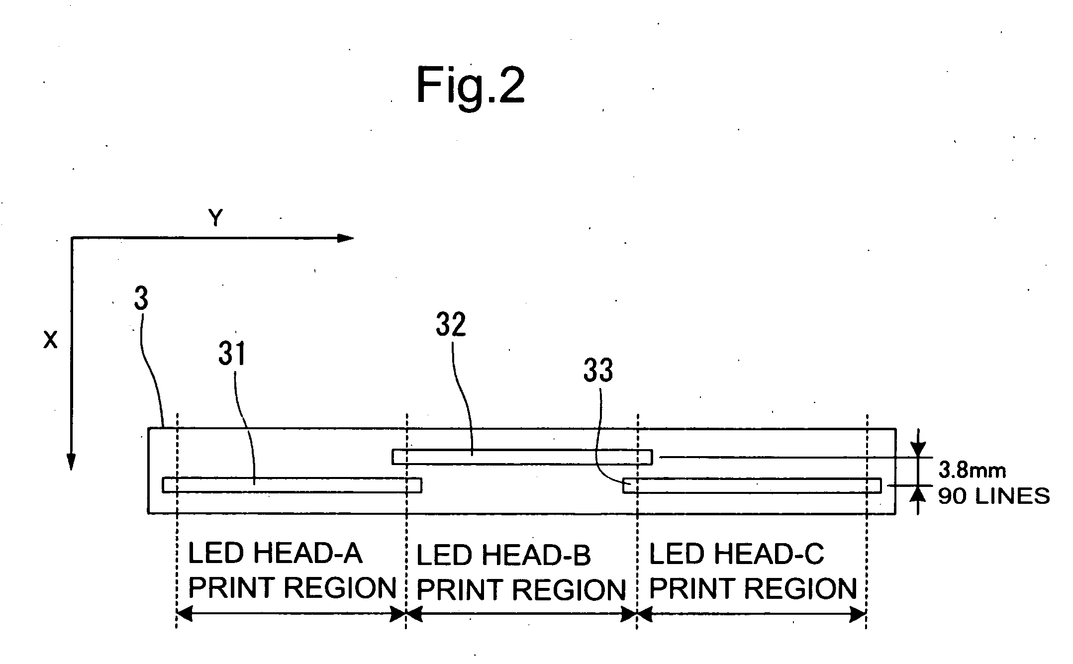
However, when the separation type LED head instead of the single type LED head is used in the LED printer device described in Japanese Patent Application Laid-open No. 2001-923226, there is a problem that normal printing is not performed because joint correction timings of the respective LED heads of the separation type LED head which are shifted in position in the sub scanning direction are changed.
In other words, there is a problem that the prints in the main scanning direction are not joined and thus the print length in each of the front end region and the rear end region cannot be normally corrected, thereby reducing printing precision (see FIG. 9B).
Method used
Image
Click on the blue label to locate the original text in one second.
Reading with bidirectional positioning of images and text.
Examples
first embodiment
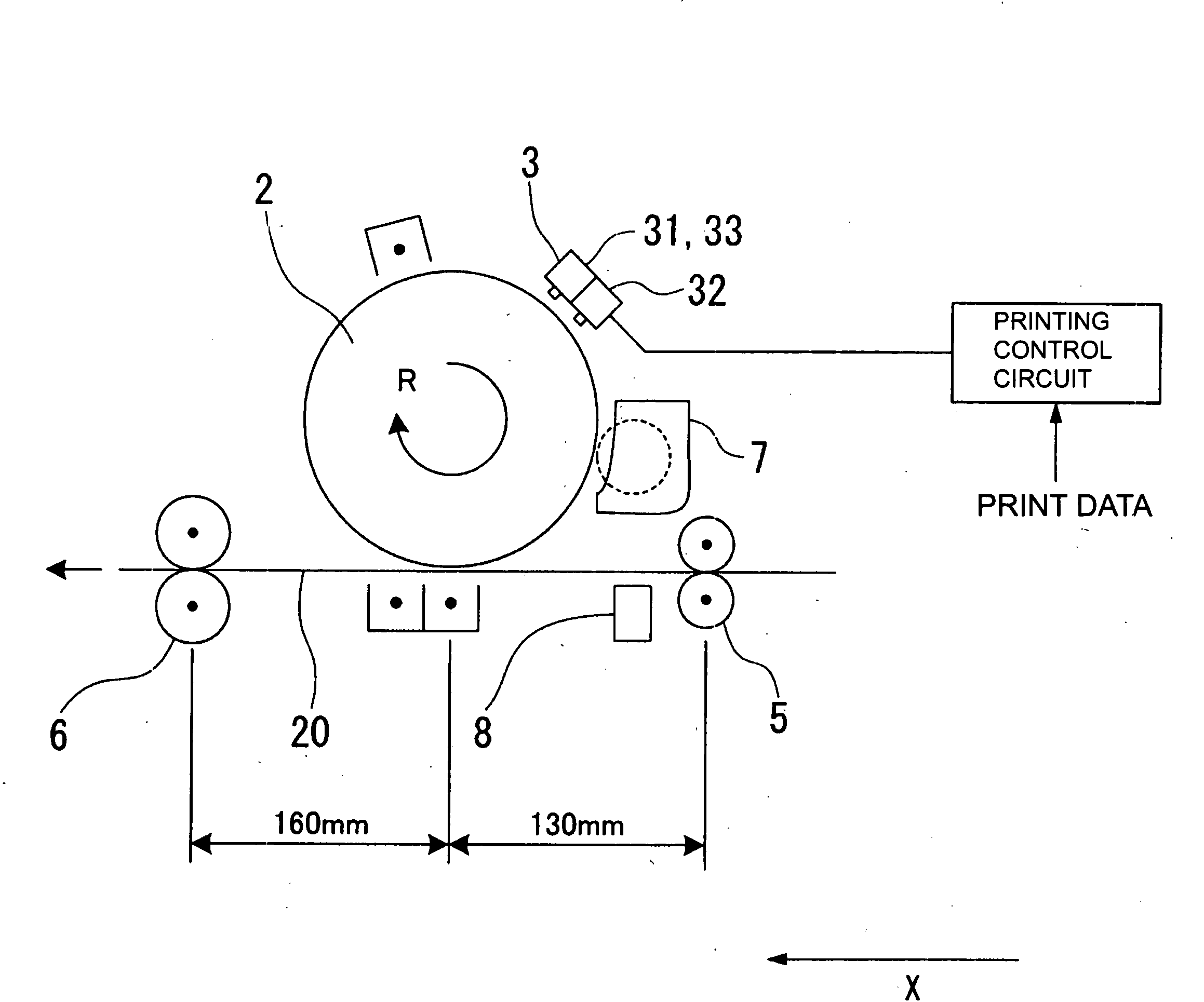
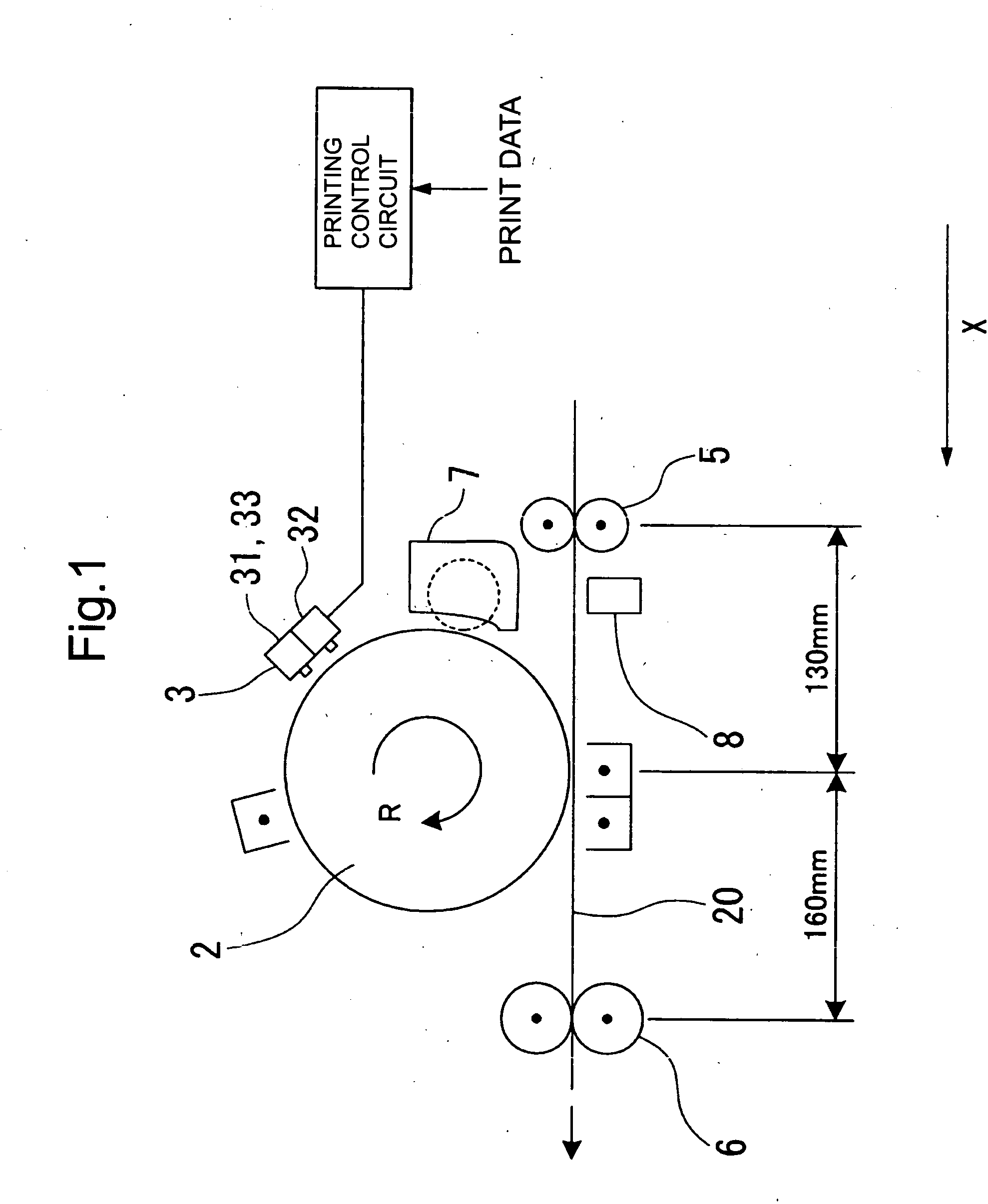
[0067]Hereinafter, an embodiment of the present invention will be described with reference to the drawings. FIG. 1 is a schematicblock diagram showing a structure of an LED printer according to the embodiment of the present invention.
[0068]The LED printer includes a photosensitive drum 2, a resist roller 5, a fixing device 6, a resist sensor 8, a separation type LED head 3, a printing control circuit 1, and a developing device 7.
[0069]The photosensitive drum 2 rotates about a rotating shaft in the sub scanning direction X at a constant rotation rate. The resist roller 5 feeds a printing medium 20 to the photosensitive drum 2 at a first constant speed. The fixing device 6 discharges the printing medium 20 from the photosensitive drum 2 at a second constant speed.
[0070]The first constant speed is different from the second constant speed. The second constant speed is faster than the first constant speed.
[0071]Note that, the printing medium 20 is a medium on which printing is performed...
second embodiment
[0150]A second embodiment will be described with reference to FIG. 8.
[0152]The CPU 201 has functions which correspond to the LINECLK value shift counter circuit 114, the AC delay value shift counter circuit 116, the B-delay value shift counter circuit 117, the L1 comparator circuit 104, and the L2 comparator circuit 105.
[0153]The RAM 202 or the ROM 203 has functions which correspond to the front end LINECLK storage section 101, the central LINECLK storage section 102, and the rear end LINECLK storage section 103.
[0154]A LINECLK register circuit 204 shown in FIG. 8 corresponds to the line-clock set frequency storage section included in the LINECLK generating circuit 109. Therefore, the LINECLK generating circuit 109 sh...
PUM
Abstract
The LED printer includes: a photosensitive drum; a resist roller for feeding a printing medium to the photosensitive drum at a first constant speed; a fixing device for discharging the printing medium from the photosensitive drum at a second constant speed; a separation type LED head arranged zigzag; and a printing control circuit for detecting a position of the printing medium fed by the resist roller or the fixing device and adjusting printing timings of the first portion LED head and the second portion LED head based on the detected position and the LED head interval. The LED printer can normally correct a print length in each of a front end region and a rear end region of a sheet.
Description
BACKGROUND OF THE INVENTION[0001]1. Technical Field[0002]The present invention relates to a technique for controlling an LED printer and, more particularly, to a technique for controlling an LED printer using a separation type LED head.[0003]2. Background Art[0004]A conventional printing process using an LED printer is performed as follows. Flash light emission (exposure) is performed using an LED head opposed to a photosensitive drum based on print data supplied from the outside to form an electrostatic latent image on the photosensitive drum. The electrostatic latent image formed on the photosensitive drum is supplied with toner and developed by a developing device. A toner image formed by developing is transferred by a transfer device onto a sheet fed from a resist roller and deposited thereon.[0005]After that, the toner deposited on the sheet is fixed to the sheet by a fixing device while the sheet is discharged, so printing is completed. Note that the LED printer is controlled ...
Claims
Application Information
Patent Timeline
Application Date:The date an application was filed.
Publication Date:The date a patent or application was officially published.
First Publication Date:The earliest publication date of a patent with the same application number.
Issue Date:Publication date of the patent grant document.
PCT Entry Date:The Entry date of PCT National Phase.
Estimated Expiry Date:The statutory expiry date of a patent right according to the Patent Law, and it is the longest term of protection that the patent right can achieve without the termination of the patent right due to other reasons(Term extension factor has been taken into account ).
Invalid Date:Actual expiry date is based on effective date or publication date of legal transaction data of invalid patent.

