Three dimensional shape reconstitution device and estimation device

a three-dimensional shape and estimation device technology, applied in static indicating devices, instruments, program control, etc., can solve the problems of inability to obtain sufficient distinguishing accuracy, difficulty in applying factorization methods to actuals, and difficulty in automatic processing, so as to reduce calculation time, enhance estimation accuracy, and stabilize estimation

Active Publication Date: 2008-10-16
DENSO CORP +1
View PDF10 Cites 15 Cited by
  • Summary
  • Abstract
  • Description
  • Claims
  • Application Information

AI Technical Summary

Benefits of technology

[0017]To solve the above problems, a first object of the present invention is to execute factorization even when unreliable data is contained in an observation matrix (feature point position sequence), and to reduce calculation time, in a three dimensional shape reconstitution device. Further, a second object of the present invention is to provide an estimation device, which can obtain stable estimation results just after the start of the processing and enhance an estimation accuracy.

Problems solved by technology

Accordingly, it is difficult for the factorization method to be applied to the actual problem that defective data often generates in the feature point position sequence (and data forming the observation matrix) due to hiding of feature points, wrong tracking, and flame-out.
Since the distinguishing is difficult, its automatic processing is difficult.
Sufficient accuracy of the distinguishing cannot be obtained.
As a result, an amount of necessary calculations disadvantageously increases.
Due to the large amount of the calculations, the conventional factorization method cannot be applied to a computing unit, having a limited calculation ability, such as a three dimensional shape reconstitution device mounted to a vehicle.
In such a device, when a model used for generating a shape model and a captured target object are the same as each other, a direction of the target object can be estimated accurately, but when the model and target object are different from each other, the estimation accuracy disadvantageously decreases.
However, disadvantageously, in the method using the individual models, the estimation accuracy is likely to be improved for every target objects, but the estimation of a direction of the target object cannot be started immediately because the learning takes long time, and the estimation accuracy decreases remarkably in case of the failure of the learning.
In the method using the average models, the estimation of a direction of a target object can be started immediately because the learning of the models is unnecessary, but some errors always occur in the estimations, and thus the estimation accuracy cannot be improved because a three-dimensional shape of the target object does not match the three dimensional shapes shown by the average models.Patent Document 1: JP-2000-113194 A (JP-3711203 B1, corresponding to U.S. Pat. No. 6,628,819)Patent Document 2: JP-2003-141552A

Method used


Image

  • Three dimensional shape reconstitution device and estimation device
  • Three dimensional shape reconstitution device and estimation device
  • Three dimensional shape reconstitution device and estimation device

Examples


first embodiment

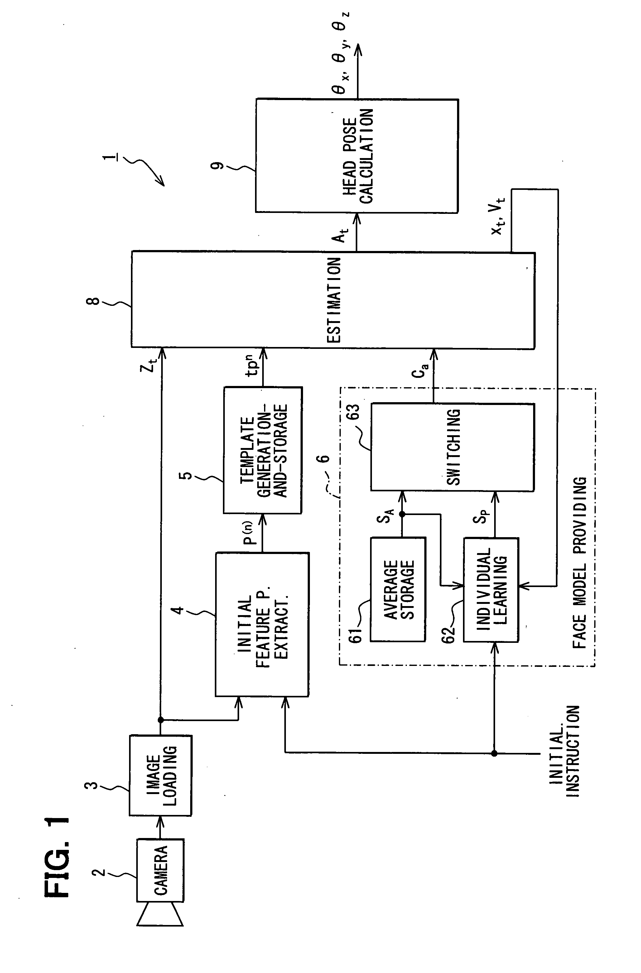
[0033]FIG. 1 is a block diagram showing an entire structure of an image processing device 1 as a three dimensional reconstitution device or estimation device according to a first embodiment of the present invention. The image processing device 1 is mounted to a subject vehicle, and obtains a head pose time-sequentially from an image of a head of a driver captured by a camera. The head pose is used for detecting inattentive driving and drowsy driving of the driver.

[0034]

[0035]The image processing device 1 is installed over or under a surface in front of a driver's seat (for example, in a meter). The image processing device 1 includes the following: a camera 2; an image loading device 3; an initial feature point extraction portion 4; a template generation-and-storage portion 5; a face model providing portion 6; an estimation portion 8; and a head pose calculation portion 9.

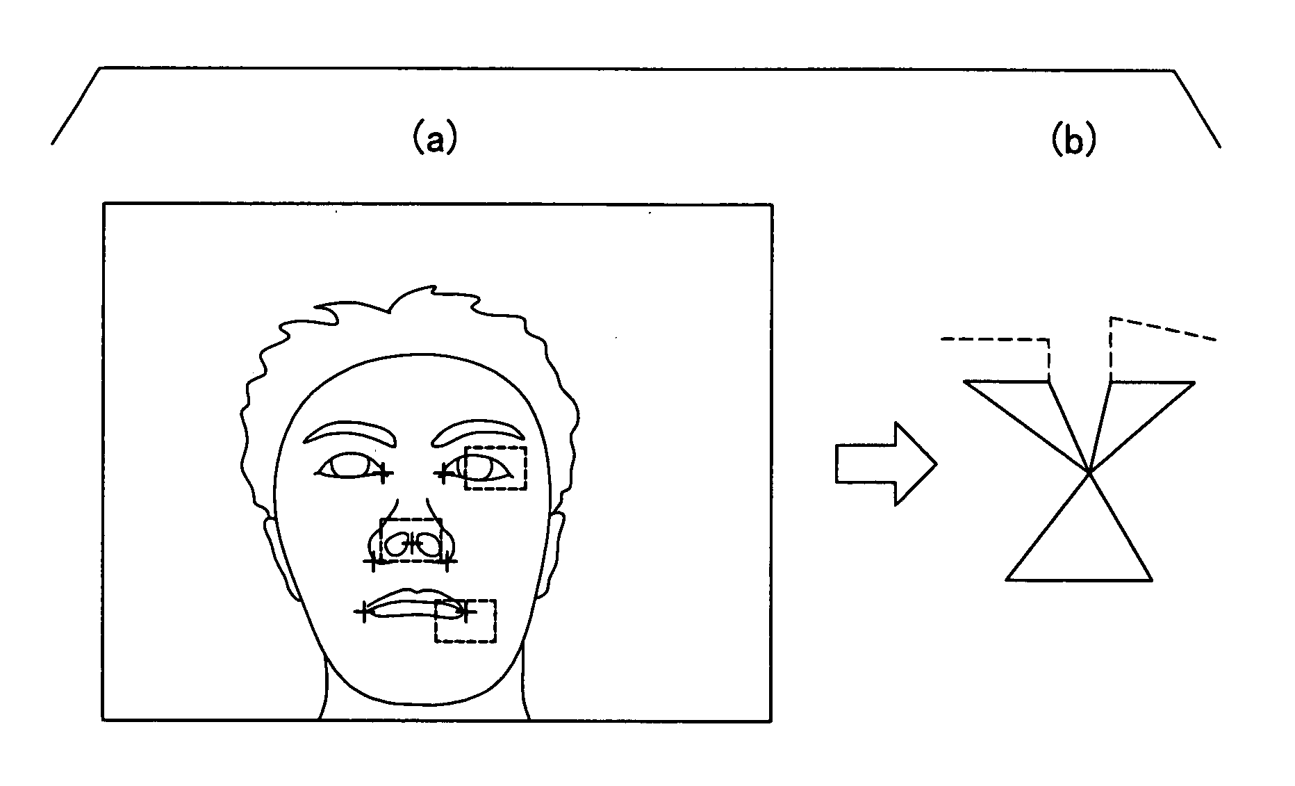
[0036]The camera 2 is configured for obtaining or capturing an image including a head of the driver as shown in F...

second embodiment

[0118]Next, a second embodiment is explained. In this embodiment, since only part of the processes in the individual face model learning portion 62 is different from those in the first embodiment, the different part is mainly explained.

[0119]

[0120]FIG. 8 is a flowchart showing the process executed by the individual face model learning portion 62. As well as in the first embodiment, this process is started by the initialization instruction. Since Steps S210 to S250 are the same as Steps S110 to S150 in the first embodiment, their explanation is omitted.

[0121]The specific number used in Step S230 may be smaller (for example, from a few tenths to a few hundredths of the specific number) than that in the first embodiment. In Step S260, the process for calculating the test distribution q(M) of the motion matrix is executed as the variational Bayes M step, and then the flow goes to Step S270.

[0122]In Step S260, specifically, in accordance with W, Q obtained in Step S240, the latest distri...


PUM


Abstract

A face model providing portion provides an stored average face model to an estimation portion estimating an affine parameter for obtaining a head pose. An individual face model learning portion obtains a result of tracking feature points by the estimation portion and learns an individual face model. The individual face model learning portion terminates the learning when a free energy of the individual face model is over a free energy of the average face model, and switches a face model provided to the estimation portion from the average face model to the individual face model. While learning the individual face mode, an observation matrix is factorized using a reliability matrix showing reliability of each observation value forming the observation matrix with emphasis on the feature point having higher reliability.

Description

CROSS REFERENCE TO RELATED APPLICATIONS[0001]This application is based on and incorporates herein by reference Japanese Patent Applications No. 2007-102914 filed on Apr. 10, 2007, and No. 2007-102915 filed on Apr. 10, 2007.FIELD OF THE INVENTION[0002]The present invention relates to a three dimensional shape reconstitution device for reconstituting a three dimensional shape of a target object from an image (two dimensional shape) of the target object, which is obtained by capturing the target image, and to an estimation device for estimating a direction of the target object in a three dimensional space from the captured image (two dimensional shape) of the target object.BACKGROUND OF THE INVENTION[0003]The factorization method is conventionally known as a method in which an image sequence of a target object is inputted, positions of multiple preset feature points are tracked on the image plane, and a three dimensional shape of the target object is reconstituted from a feature point ...

Claims


Application Information

Patent Timeline
Patent Type & Authority Applications(United States)
IPC IPC(8): G06K9/00G06K9/46
CPCG06K9/00248G06K9/00281G06V40/165G06V40/171
Inventor SHIMIZU, MIKIOFUKAYA, NAOKIBANDO, TAKASHISHIBATA, TOMOHIROISHII, SHIN
Owner DENSO CORP
Why Eureka
Try Eureka