
Printer and feeding apparatus for the same

Active Publication Date: 2008-10-16
MIMAKI ENG
View PDF9 Cites 8 Cited by
  • Summary
  • Abstract
  • Description
  • Claims
  • Application Information

AI Technical Summary

Benefits of technology

[0005]In a printer for printing on a sheet-like print medium, in order to improve the accuracy in feeding the print medium, it is known to place a guide member, which is formed in a cylindrical shape extending in the width direction of the print medium, in the way of feeding the print medium from a sheet supplying member to a print head, at a position capable of smoothly feeding the print medium to the print head. For example, JP-A-2003-252491 discloses such a printer. The contents of this publication are incorporated herein by reference in their entirety. Conventionally, a print medium is fed from a sheet supplying member to a print head by rotating a guide member 200 (see FIG. 5), which is formed in a cylindrical shape extending in the width direction for substantially the same length as the dimension in the width direction of the print medium and is rotatably disposed, regardless of the dimension in the width direction of the print medium even when the sheet-like print medium is large (for example, about 3 meters) in width.
[0008]According to another aspect of the present invention, a feeding apparatus for a printer includes a guide member which is configured to guide a sheet print medium to feed the sheet print medium onto an upper surface of a supporting member on which a print head is configured to print. The guide member includes at least one guide collar around which the sheet print medium is wound and a guide bar provided in the at least one guide collar so that the at least one guide collar is rotatable around the guide bar.
[0008]According to another aspect of the present invention, a feeding apparatus for a printer includes a guide member which is configured to guide a sheet print medium to feed the sheet print medium onto an upper surface of a supporting member on which a print head is configured to print. The guide member includes at least one guide collar around which the sheet print medium is wound and a guide bar provided in the at least one guide collar so that the at least one guide collar is rotatable around the guide bar.

Problems solved by technology

Since the guide member 200 extends in the width direction for substantially the same length as the width of the print medium, however, twist and warpage are easily occurred in manufacturing the guide member 200 and an installation error is also easily caused in installing the guide member 200 to a printer because the guide member 200 is long in the width direction.
Therefore, there is such a problem that the accuracy in feeding the print medium is deteriorated.

Method used


Image

  • Printer and feeding apparatus for the same
  • Printer and feeding apparatus for the same
  • Printer and feeding apparatus for the same

Examples


Embodiment Construction

[0015]The embodiments will now be described with reference to the accompanying drawings, wherein like reference numerals designate corresponding or identical elements throughout the various drawings.

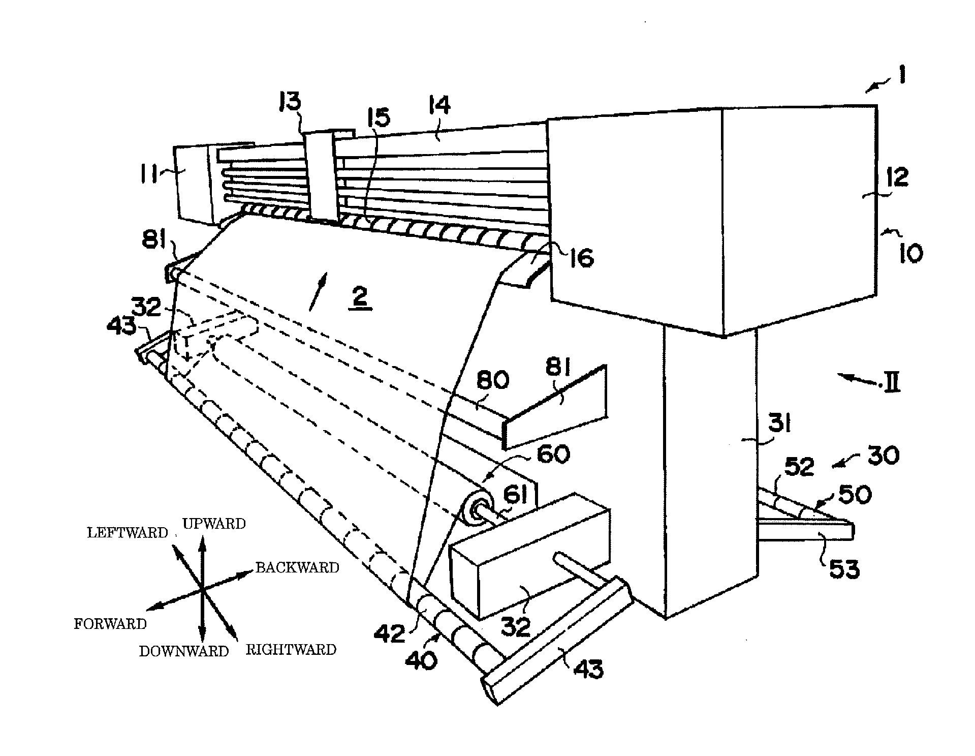
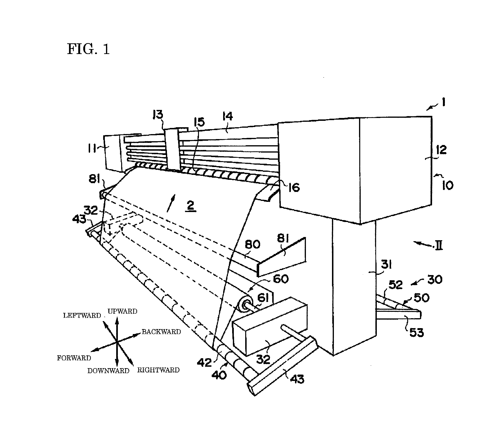
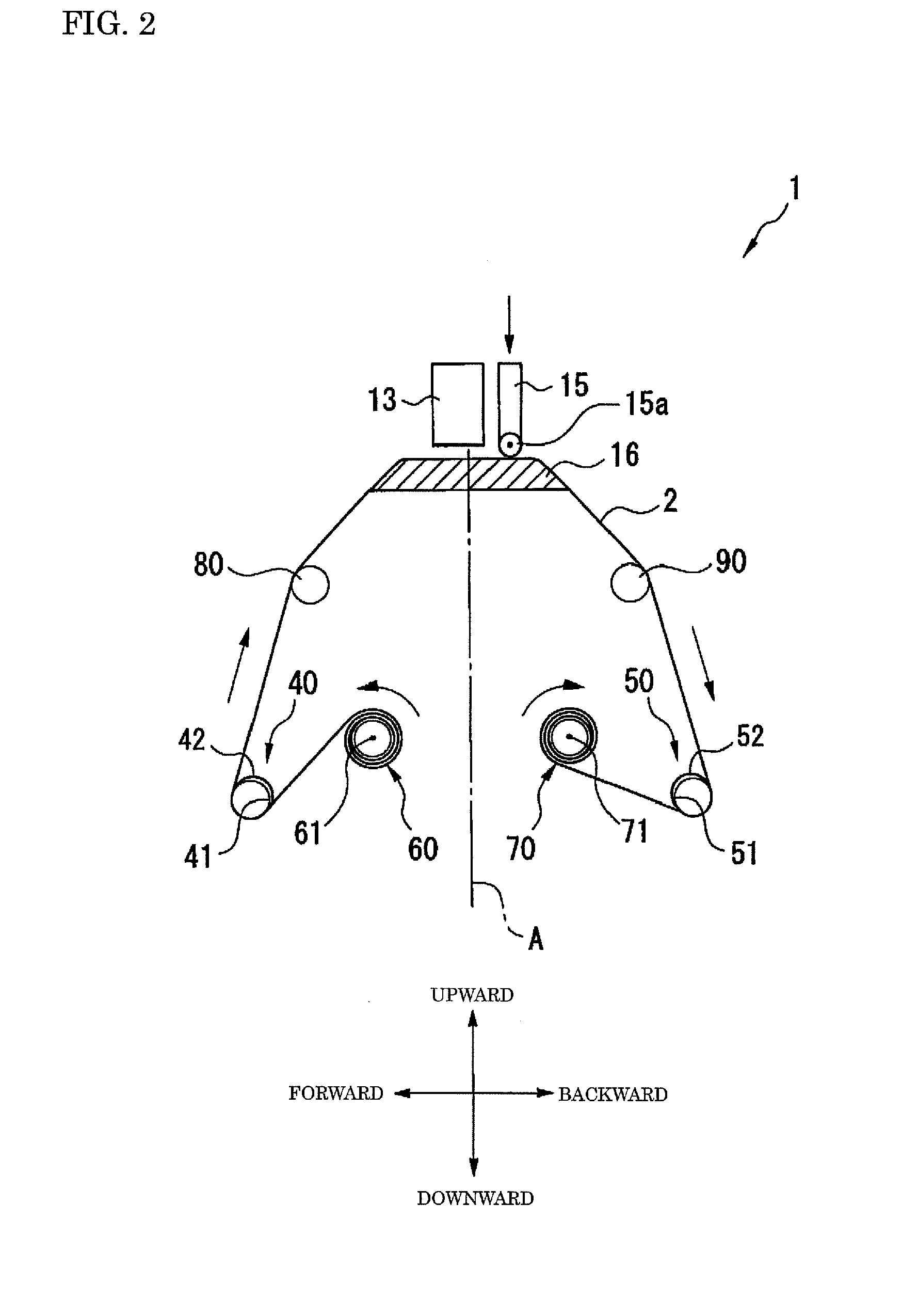
[0016]Hereinafter, a printer 1 according to an embodiment of the present invention will be described with reference to FIG. 1 through FIG. 4. For ease of explanation, leftward, rightward, forward (front), backward (rear), upward and downward directions are defined as the directions of arrows in FIG. 1. As shown in FIG. 1, the printer 1 is a printing apparatus for printing by ejecting liquid ink droplets to a sheet-like print medium 2 which is about 3 meter in the left-right (width) direction and which is carried in a state wound into a roll. The printer 1 includes a printing section 10 for conducting the printing process which is disposed in an upper portion of the printer 1 and a retaining section 30 which is disposed in a lower portion of the printer 1.

[0017]The printing section 10 mai...


PUM


Abstract

A printer includes a supporting member, a print head and a guide member. The supporting member is configured to support a sheet print medium on an upper surface of the supporting member. The print head is provided to print on the sheet print medium fed onto the upper surface of the supporting member. The guide member is configured to guide the sheet print medium to feed the sheet print medium onto the upper surface of the supporting member. The guide member includes at least one guide collar around which the sheet print medium is wound and a guide bar provided in the at least one guide collar so that the at least one guide collar is rotatable around the guide bar.

Description

CROSS-REFERENCE TO RELATED APPLICATIONS[0001]The present application claims priority under 35 U.S.C. § 119 to Japanese Patent Application No. 2007-097219, filed Apr. 3, 2007, entitled “Printer Apparatus.” The contents of this application are incorporated herein by reference in their entirety.BACKGROUND OF THE INVENTION[0002]1. Field of the Invention[0003]The present invention relates to a printer and a feeding apparatus for the printer.[0004]2. Discussion of the Background[0005]In a printer for printing on a sheet-like print medium, in order to improve the accuracy in feeding the print medium, it is known to place a guide member, which is formed in a cylindrical shape extending in the width direction of the print medium, in the way of feeding the print medium from a sheet supplying member to a print head, at a position capable of smoothly feeding the print medium to the print head. For example, JP-A-2003-252491 discloses such a printer. The contents of this publication are incorpora...

Claims


Application Information

Patent Timeline
IPC IPC(8): B41J13/00
CPCB41J11/001B41J11/0045B41J15/165B65H16/08B41J15/04
Inventor KANBARA, TAKAAKI
Owner MIMAKI ENG
Features
  • Generate Ideas
  • Intellectual Property
  • Life Sciences
  • Materials
  • Tech Scout
  • Unparalleled Data Quality
  • Higher Quality Content
  • 60% Fewer Hallucinations
Learn More