External Fixator for Osteosynthesis or Bone Gap Manipulation

Inactive Publication Date: 2008-10-16
DEPUY SYNTHES PROD INC
View PDF12 Cites 12 Cited by
  • Summary
  • Abstract
  • Description
  • Claims
  • Application Information

AI Technical Summary

Benefits of technology

[0010]The object of the invention is the development of an osteosynthetic connection system which permits simple, rapid and safe handling in the region of the sternum, particularly in cases of heart surgery. Because of its location, the system is subject to very high intermittent forces from concomitant thoracic movement if the patient experiences strong inhalation or exhalation or is coughing. The anchoring of the system presents another problem. The sternum

Problems solved by technology

Because of its location, the system is subject to very high intermittent forces from concomitant thoracic movement if the patient experiences strong inhalation or exhalation or is coughing.
The anchoring of the system presents another problem.
The anchoring may be torn out, and there is al

Method used


Image

  • External Fixator for Osteosynthesis or Bone Gap Manipulation
  • External Fixator for Osteosynthesis or Bone Gap Manipulation
  • External Fixator for Osteosynthesis or Bone Gap Manipulation

Examples


Example

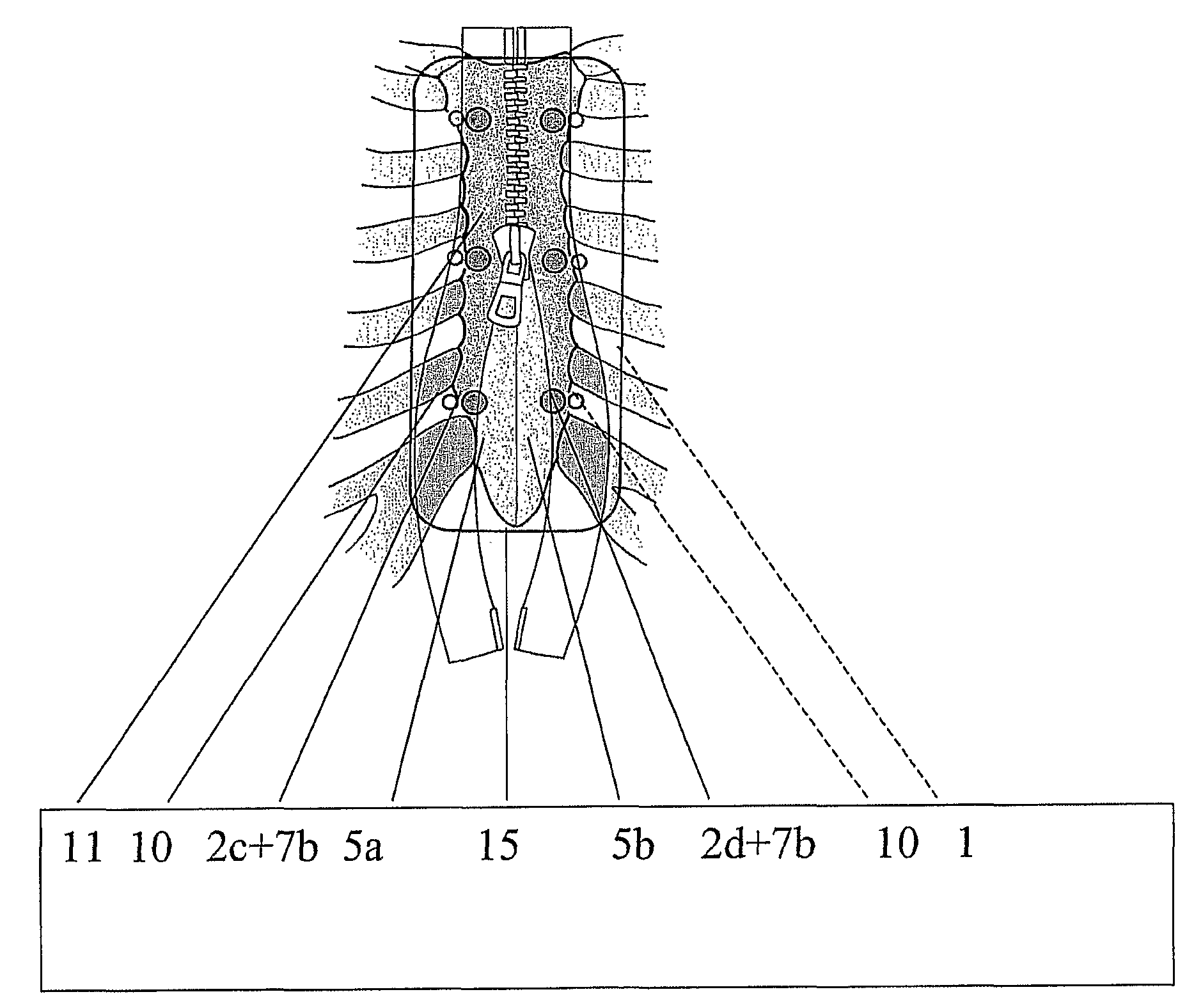
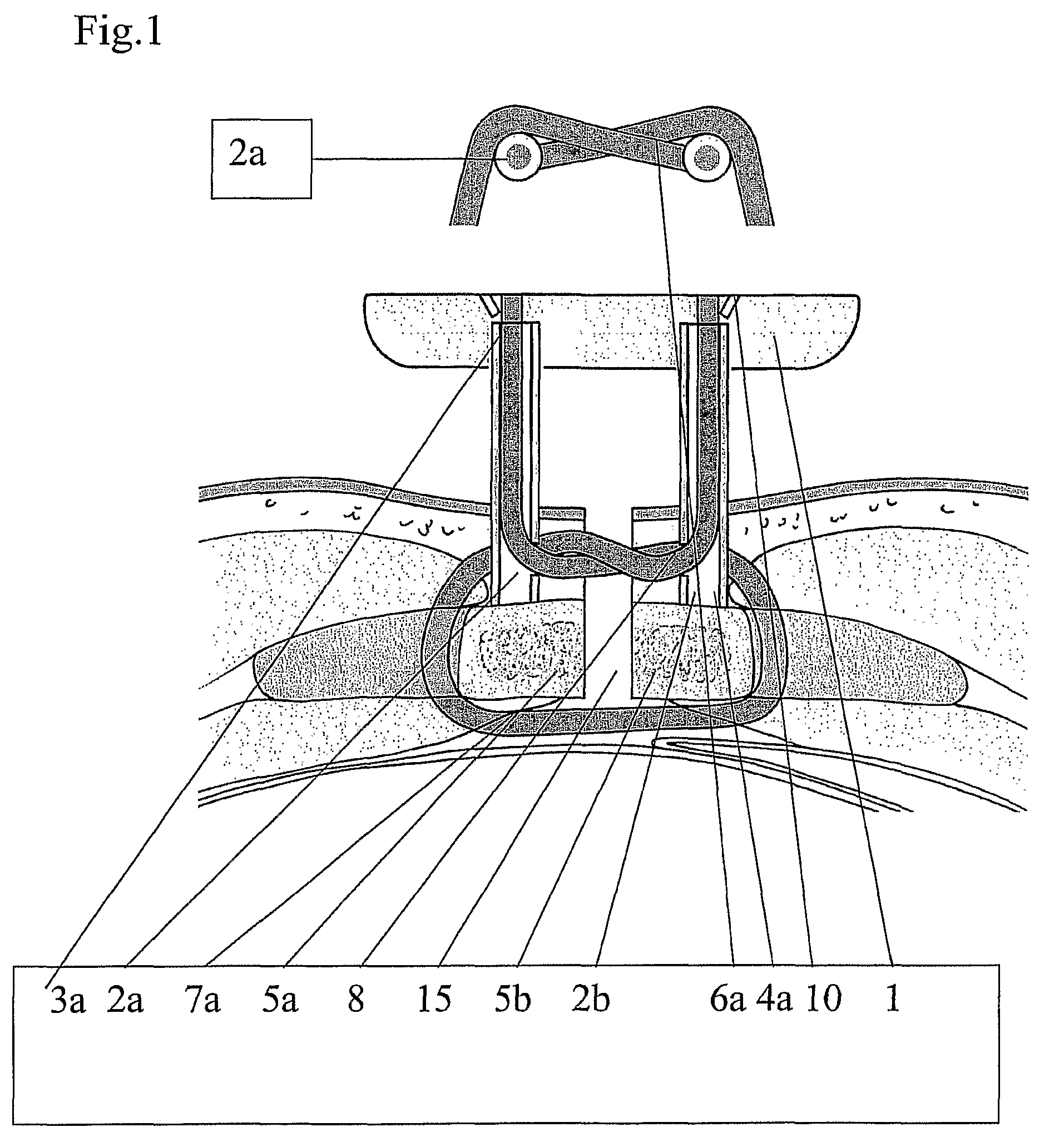
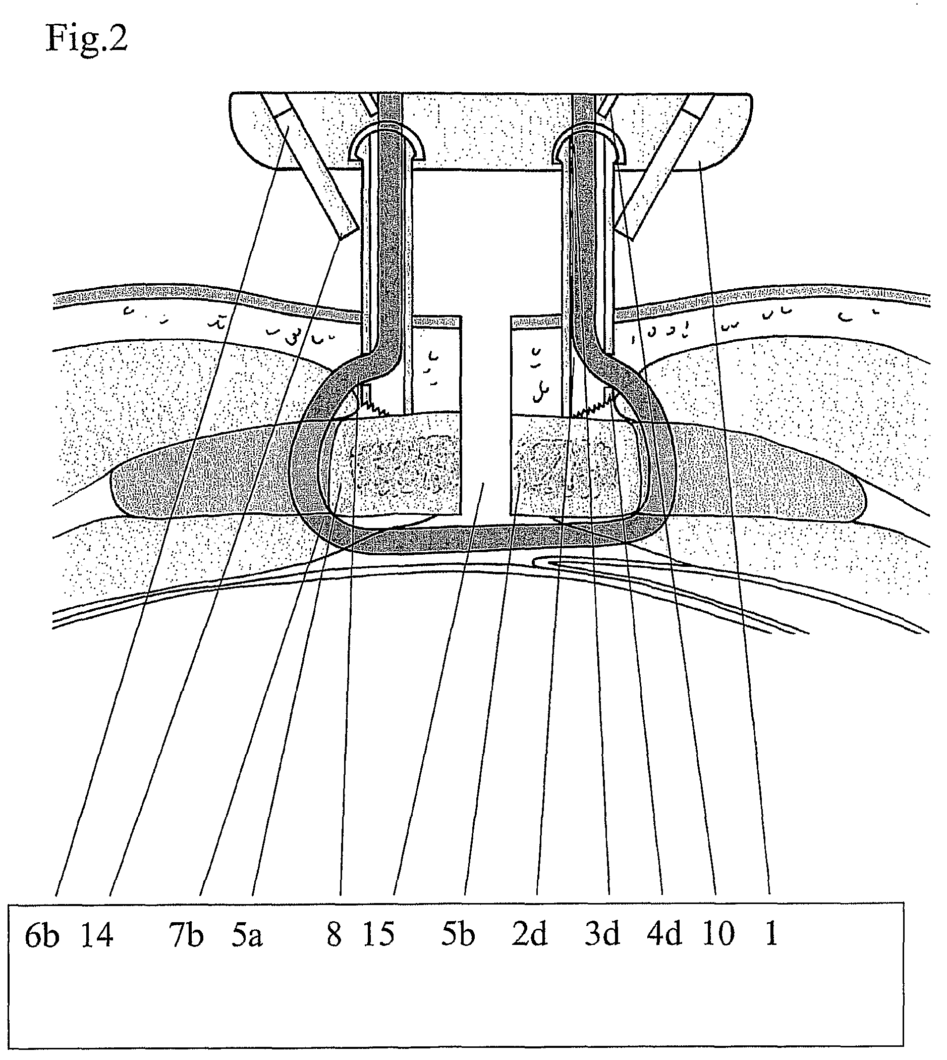
[0051]Two models of an external fixator according to the invention, having different cable paths and methods of fixing, are presented:

[0052]FIG. 1 shows an attachment with cross-loop 7a:

[0053]In the lower part, a section along the transverse plane through a patient, in particular through the sternum, with inserted external fixator is shown. A section along a frontal plane is shown above this, where only loop 7a simultaneously exerts the control tension on connecting elements 2a and 2b and thus applies more or less pressure to a bone gap 15.

[0054]The loop 7a is placed between connecting element 2a, bone part 5a and connecting element 2b. Second bone part 5b is introduced basally and medially. In the assembled state, said loop therefore consists of a crossed carbon fibre cable threaded into the hollow connecting elements 2a and 2b, three or four of which are used per bone-part 5a or 5b. The retaining ends 3a and 3b of the connecting elements are fastened to plate-like retaining membe...


PUM


Abstract

The invention relates to an external fixator which has a retaining member (1) and connecting elements (2) which can be connected without screws to a bone or bone parts (5), in particular to both halves of an opened sternum, and provide possibilities for increasing or reducing the compressive stress between the two bone parts or sternum halves.

Description

[0001]This application is a national stage application of PCT / IB2005 / 000826, filed Mar. 30, 2005 which claims priority to PCT / IB2004 / 001008, filed Apr. 1, 2004.FIELD OF THE INVENTION[0002]The invention relates to an external fixator for osteosynthesis or bone gap manipulation, comprising an external retaining member and connecting elements with retaining ends held in the retaining member and with contact ends to be placed on the bone for connecting the retaining member to the bone or to bone parts. The invention relates in particular to an external fixator for closing a dislocated bone and the parts thereof, for example a sternum which has been cut through.BACKGROUND OF THE INVENTION[0003]Document IL-A-122418 / 2, dated Feb. 12, 1997, describes such an external fixator which consists of an external rod as a retaining member, to which threaded rods are screwed as connecting elements. There are two screwable plates on each of the contact ends of the threaded rods, one of which comes to ...

Claims


Application Information

Patent Timeline
IPC IPC(8): A61B17/03A61B17/00A61B17/64A61B17/82
CPCA61B17/6433A61B17/823
Inventor RICHTER, JENSPLASS, ANDREHAEUSSLER, ACHIMGRUENENFELDER, JUERGZUEND, GREGORTURINA, MARKO
Owner DEPUY SYNTHES PROD INC
Why Eureka
Try Eureka