
Non-rectilinear lead and a system for deep electrical neurostimulation including such a lead

a non-rectilinear lead and deep electrical neurostimulation technology, applied in the field of brain electrical stimulation, can solve the problems of compromising the therapeutic effect, the tip becoming slightly displaced, and not always making it easy to access the region of therapeutic interest, so as to achieve the effect of not injuring tissue structures

Active Publication Date: 2008-10-16
COMMISSARIAT A LENERGIE ATOMIQUE ET AUX ENERGIES ALTERNATIVES
View PDF11 Cites 5 Cited by
  • Summary
  • Abstract
  • Description
  • Claims
  • Application Information

AI Technical Summary

Benefits of technology

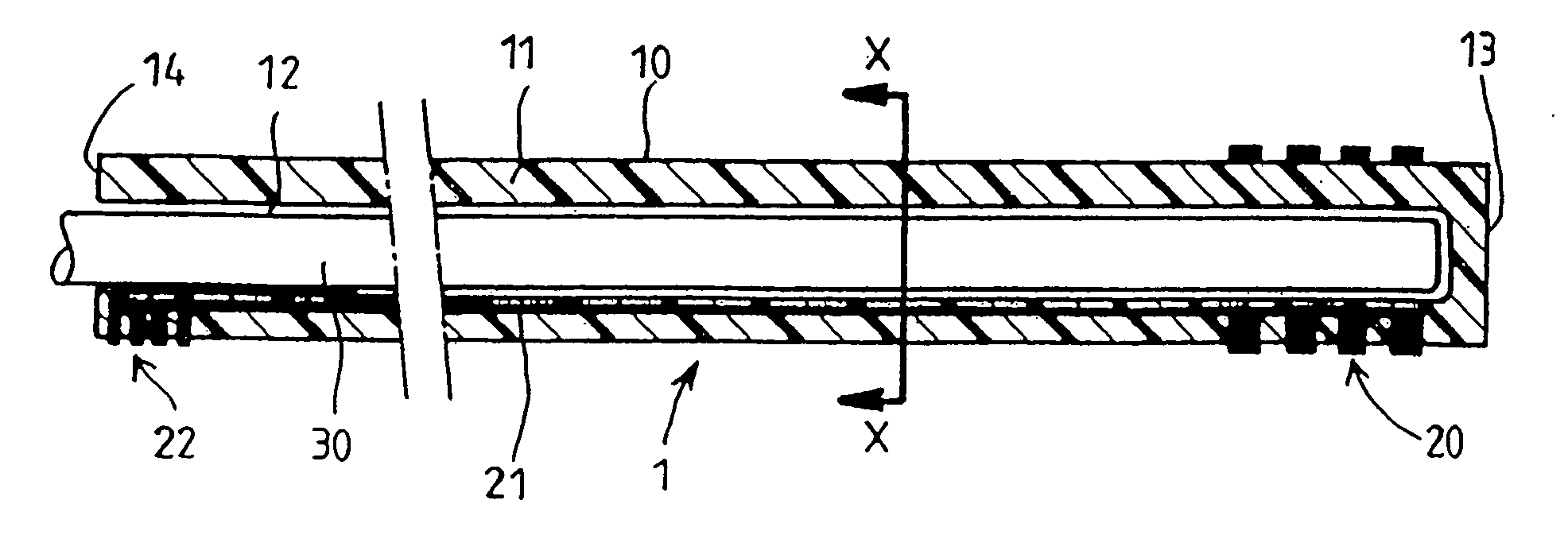
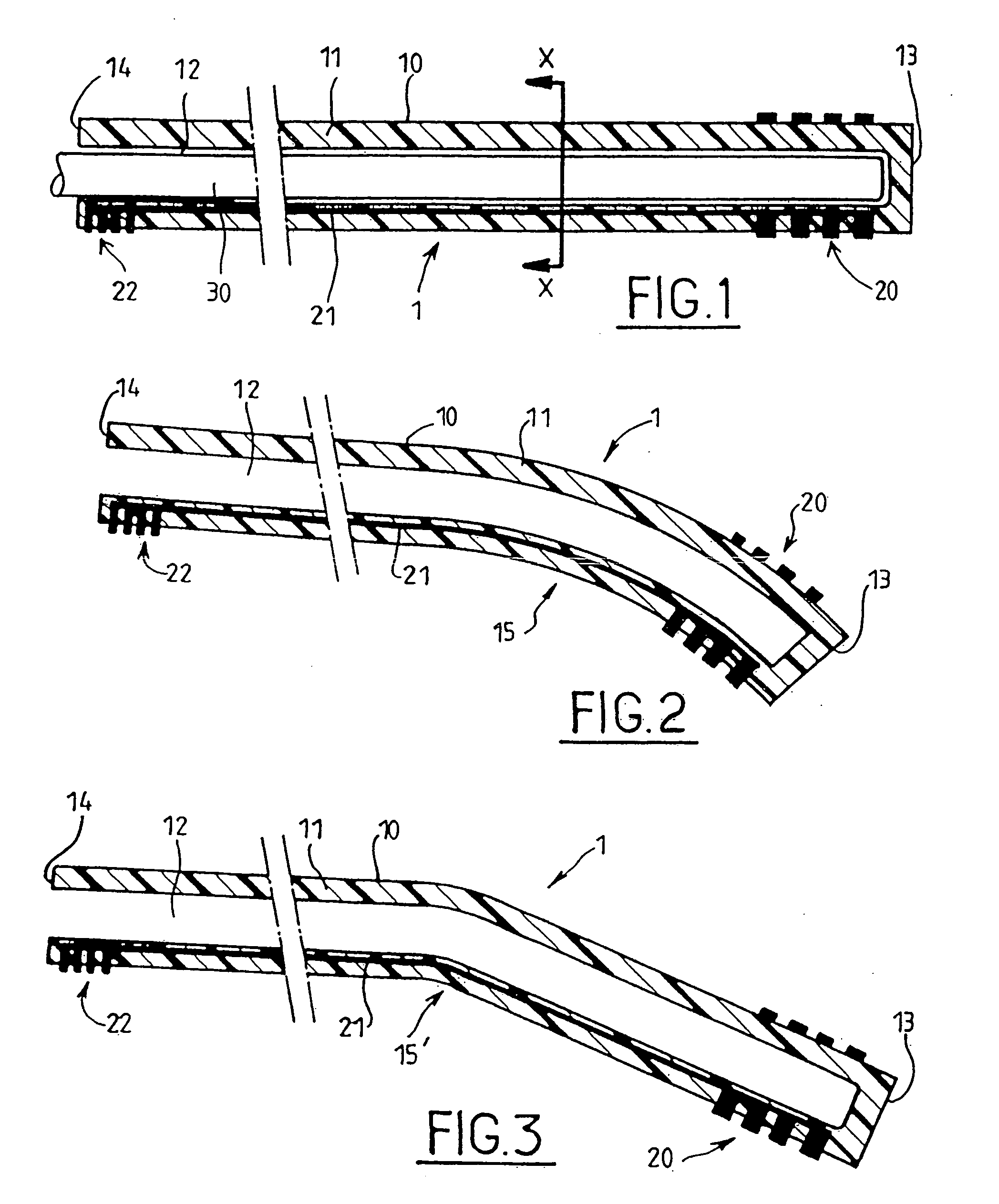
[0012]The bend that characterizes the lead of the invention makes it possible to reach regions for stimulation that would not be easily accessible using a lead of the type known in the prior art, inside cavities where the end of the lead can return to its initial shape without injuring tissue structures. The bend may be sharp or progressive, forming an angle of less than 90°, and preferably lying in the range 10° to 50°, and it may present a radius of curvature lying in the range 1 millimeter (mm) to 5 centimeters (cm), approximately.
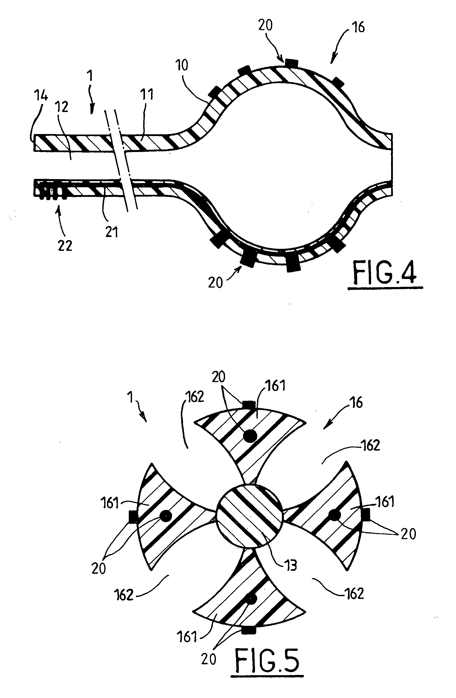
[0013]In addition, said tubular body presents, close to its distal end, a region that, when at equilibrium, forms a balloon, and that is shaped in such a manner as to lengthen and take on a configuration that is substantially linear when said stylet is inserted into the lumen. In this way, the lead, while in its linear configuration, can be inserted in the inside of a cavity in the body of a patient, and then it can be blocked inside said cavity by extracting the stylet so as to enable the lead to return to its equilibrium balloon shape. Since the balloon is situated at the distal end of the lead, i.e. at its tip, the balloon also performs a safety function, preventing said tip from injuring the parenchyma of the brain.

Problems solved by technology

Nevertheless, given the constraints that limit the insertion paths that can be selected for being followed by the lead without giving rise to unacceptable lesions in brain tissue, such a shape does not always make it easy to access regions that present therapeutic interest.
In addition, since a lead for deep brain electrical stimulation is implanted permanently for a duration of several years, there is a major risk of its tip becoming slightly displaced over time, thereby compromising its therapeutic effectiveness.
However, it is less suitable for permanent implantation since it is difficult to extract the cannula alone from the patient's skull while leaving the lead in place.
In addition, using an insertion cannula of outside diameter that is necessarily greater than that of the lead itself makes the implantation operation more traumatic.

Method used


Image

  • Non-rectilinear lead and a system for deep electrical neurostimulation including such a lead
  • Non-rectilinear lead and a system for deep electrical neurostimulation including such a lead
  • Non-rectilinear lead and a system for deep electrical neurostimulation including such a lead

Examples


fourth embodiment

[0045]Whatever the embodiment under consideration, the material from which the tubular body 10 of the lead 1 is made needs to be sufficiently flexible and elastic to be able to follow the shape of the stylet 30 by deforming reversibly when the stylet is inserted into the lumen 12. Thus, inserting the stylet 30 causes the lead to straighten out. In the third or the fourth embodiment, the tip of the stylet 30 also comes to bear against the closed distal end 13 of the tubular body 10, thereby causing it to be lengthened; the lengthening preferably occurs in the balloon-shaped region 16 and in such a manner that the lead takes on a configuration that is substantially linear.

[0046]In the third embodiment (FIG. 4), the side wall 11 can be of reduced thickness in its balloon-shaped region 16, so as to ensure that the above-mentioned preferred lengthening occurs when the stylet 30 is inserted.

[0047]The fourth embodiment of the invention (FIG. 5) being wherein, in its balloon-shaped region 1...

second embodiment

[0048]The balloon 16 performs three functions. Firstly, it enables the lead to be blocked inside a ventricle of the brain. Secondly, it prevents the tip of the lead from penetrating into the parenchyma of the patient's brain and injuring it, as a result of some involuntary movement. Thirdly, electrodes 20 can be disposed on the balloon so as to make it possible to stimulate a region of the brain that is more extensive than when using the first or the second embodiment; in this case, the equilibrium shape of the balloon can be adapted to that of the cavity.

[0049]The use of a balloon of the type shown in FIGS. 4 and 5 can also be advantageous when using a rectilinear lead that does not present a bend.

[0050]Since it is designed to be inserted in the body of a patient, and more particularly in the patient's brain, the tubular body 10 needs to be made entirely, or at least so far as its outer portion is concerned, out of a material that is biocompatible. Biocompatible materials presentin...


PUM


Abstract

A lead for deep brain electrical stimulation, to be inserted into liquid cavities, such as ventricles, or cysternae or subarachnoidal spaces, the lead comprising: a tubular body of biocompatible material having a side wall defining a lumen, said tubular body being suitable for being inserted over at least a fraction of its length into the inside of a patient's body in order to reach a region for stimulation; electrodes disposed close to a distal end of the tubular body; and a rigid stylet for inserting removably into the lumen of said tubular body; the lead being wherein said tubular body has an equilibrium shape that is not rectilinear, being different from the shape of the stylet and presenting one and only one bend, and that is sufficiently flexible and elastic to follow the shape of said stylet by deforming reversibly when the stylet is inserted into the lumen. A deep electrical neurostimulation system comprising an electrical pulse generator and at least one such lead having its electrodes electrically connected to said generator.

Description

[0001]The invention relates to a lead for deep brain electrical stimulation, and also to a deep brain electrical stimulation system including at least one such lead.BACKGROUND OF THE INVENTION[0002]Deep brain electrical stimulation is a therapeutic technique comprising the implantation of a medical device known as a brain stimulator that serves to send electrical pulses to specific portions of the brain, by means of leads for electrical stimulation implanted in the appropriate neural structures. For example, stimulating the thalamic nuclei or the subthalamic nuclei can be useful in treating motor disorders such as tremor as caused in particular by Parkinson's disease (see the article by A-L. Benabid, P. Pollak, C. Gervason, D. Hoffmann, D-M. Gao, M. Hommel, J-E. Perret, and J. de Rougemont “Long-term suppression of tremor by chronic stimulation of the ventral intermediate thalamic nucleus”, The Lancet, Vol. 337, No. 8738, Feb. 16, 1991, pp. 403-406). In addition, stimulation of the ...

Claims


Application Information

Patent Timeline
IPC IPC(8): A61N1/04
CPCA61N1/0529A61N1/0534
Inventor BENABID, ALIM-LOUISSAUTER-STARACE, FABIENCAILLAT, PATRICECHABARDES, STEPHAN
Owner COMMISSARIAT A LENERGIE ATOMIQUE ET AUX ENERGIES ALTERNATIVES
Learn More