Jewelry Clasp

a clasp and jewelry technology, applied in the field of jewelry clasps, can solve the problems of undesired interference or blockage of the clasp portion of such bracelets or necklaces with the installation of such decorative beads on the bracelet or necklace's strand, and achieve the effect of preventing the installation of decorative beads

Inactive Publication Date: 2008-10-23
H K C J ASIA
View PDF5 Cites 14 Cited by
  • Summary
  • Abstract
  • Description
  • Claims
  • Application Information

AI Technical Summary

Benefits of technology

[0011]In use of the instant inventive jewelry clasp, the eyes of a plurality of decorative beads may be extended over the helically threaded lug and thence onto the strand element. Thereafter, the helically threaded lug, along with its attached strand end, may be threadedly mounted within the clasp's helically threaded void. Upon such threaded mounting, the clasp effectively functions as a bead retaining slide stop. In order to remove and interchange beads,

Problems solved by technology

A drawback or deficiency of common bracelets or necklaces, such as described above, is that the clasp portions of such bracelets

Method used


Image

  • Jewelry Clasp
  • Jewelry Clasp
  • Jewelry Clasp

Examples


Embodiment Construction

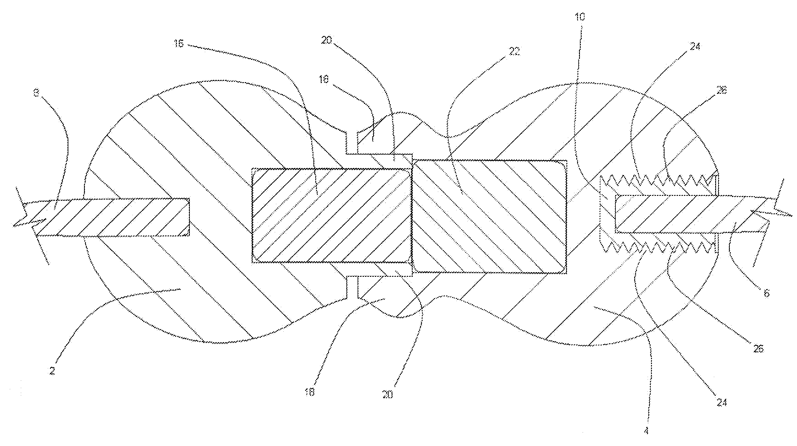
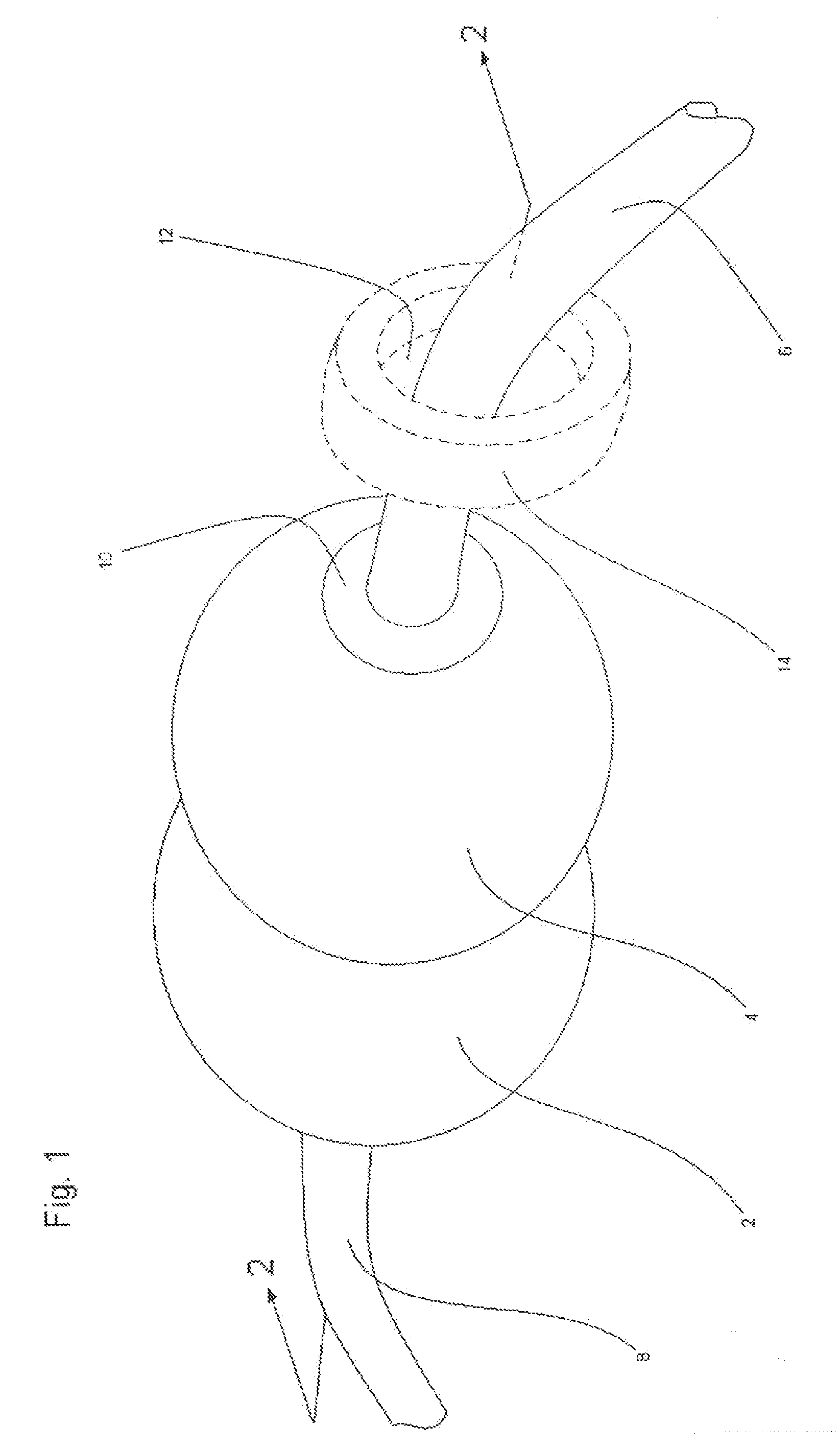
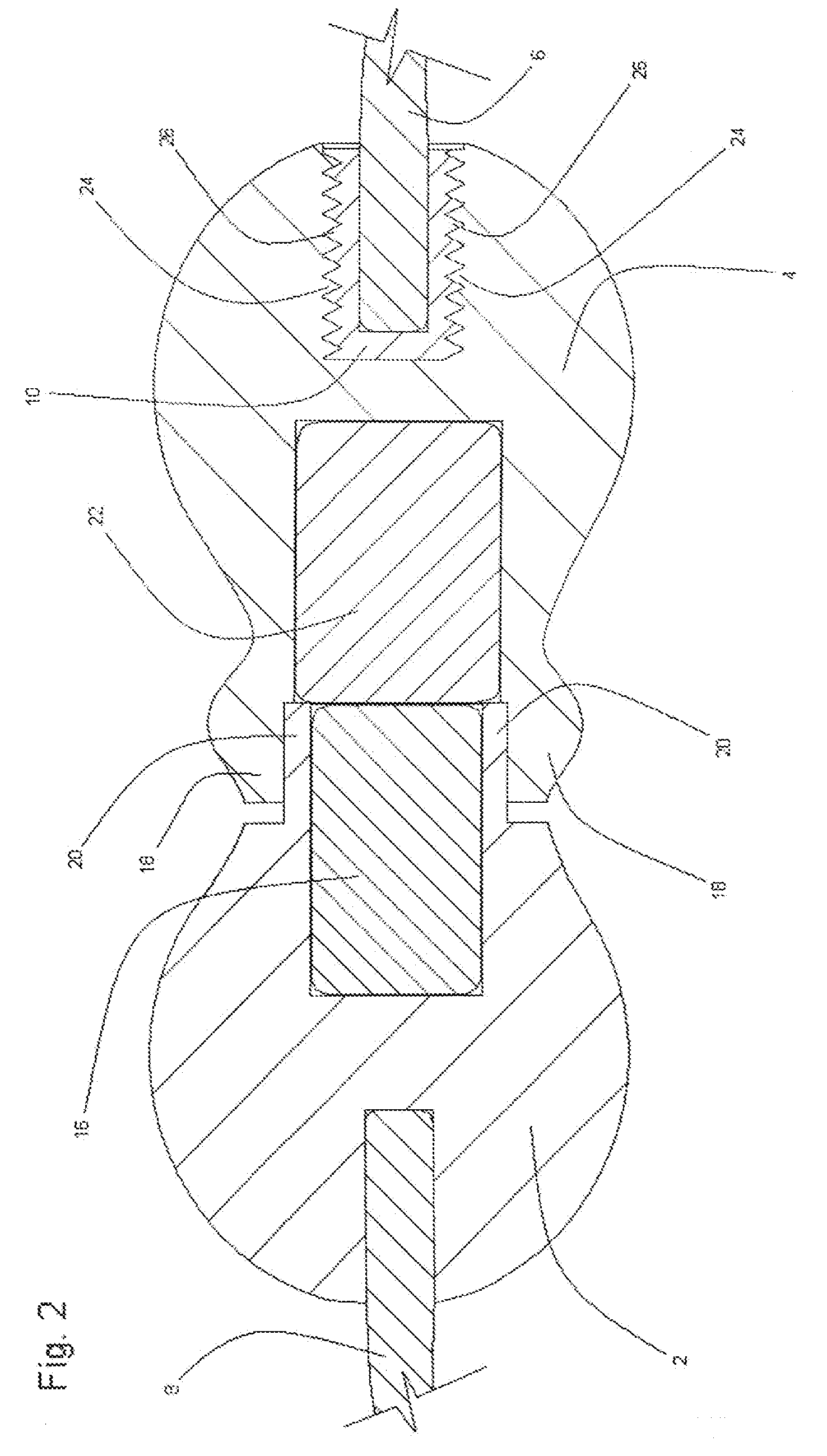
[0021]Referring now to the drawings, and in particular to FIG. 1, a magnetic jewelry clasp configuration of the instant invention is depicted, such clasp including a left body portion 2 and a right body portion 4. Referring further simultaneously to FIG. 3, the left body portion 2 of the clasp preferably includes a strand end receiving socket 28, and a rightwardly extending magnet receiving annular ridge 20, such ridge defining a rightwardly opening magnet receiving socket 30. Referring further simultaneously to FIG. 2, a left end 8 of a flexible strand is preferably extended into socket 28 and is preferably fixedly and permanently mounted therein by means of compression fitting, adhesive bonding, or soldering. A magnet 16 is preferably extended leftwardly into socket 30, and such magnet 16 is preferably permanently and fixedly mounted therein by means of compression fitting or adhesive bonding.

[0022]Referring simultaneously to FIGS. 1, 2, and 4, the right body portion 4 of the magn...


PUM


Abstract

A jewelry assembly incorporating a body portion, the body portion being halved, each half of the body portion including a magnetic fastener half; a strand anchoring pin and socket joint fixedly attached to one of the clasp's halves; a helically threaded void extending into the other of the clasp's halves; a helically threaded lug fitted for threaded engagement with the helically threaded void, and a flexible bead supporting strand spanning between and interconnecting the body portion's halves.

Description

REFERENCE TO PREVIOUSLY FILED PROVISIONAL APPLICATION[0001]The following non-provisional patent application is directed to and claims priority from, and claims the benefit of the filing date of Provisional Patent Application No. 60 / 735,435 filed Apr. 24, 2006, with the U.S. Patent and Trademark Office. The inventor under said Application No. 60 / 745,435 and the inventor under the instant Application are one and the same.[0002]That all drawings and sections of said Provisional Application are identical to the instant Application.FIELD OF THE INVENTION[0003]This invention relates to jewelry clasps. More particularly, this invention relates to jewelry clasps which are utilized for securing bead bearing bracelets or necklaces about wearer's wrists or necks.BACKGROUND OF THE INVENTION[0004]Common bracelet or necklace clasps such as magnetic clasps, spring ring clasps, and “lobster claw” clasps perform the function of securing a flexible strand bracelet or necklace about a wearer's wrist o...

Claims


Application Information

Patent Timeline
IPC IPC(8): A44C5/00A44C21/00
CPCA44C5/2076A44D2203/00Y10T24/44641Y10T24/32Y10S63/90
Inventor CHAN, LOK
Owner H K C J ASIA
Why Eureka
Try Eureka