Microfluidic Device with Porous Membrane and an Unbranched Channel

a microfluidic device and porous membrane technology, applied in the field of microfluidic devices, can solve problems such as inability to guarantee, and achieve the effect of minimizing the risk of contamination and sufficient membrane resolution

Inactive Publication Date: 2008-10-23
KONINKLIJKE PHILIPS ELECTRONICS NV
View PDF10 Cites 17 Cited by
  • Summary
  • Abstract
  • Description
  • Claims
  • Application Information

AI Technical Summary

Benefits of technology

[0030]In a special embodiment, at least one of the first and second housing parts comprises an optical element, preferably as an integral part of said at least one of the first and second housing parts. The microfluidic device serves to detect substances in a sample fluid, by passing the sample fluid through a membrane with spots. Subsequently, the spots are inspected to determine whether or not the sample fluid actually contained the substance(s) that was( / were) to be detected by the respective spot(s). Providing an optical element may assist in surveying the spots. In particular, the optical element comprises an optical window or a lens array. This may allow a clear view with sufficient resolution of the membrane with the spots, and even with a kind of magnification by the lenses if desired. The optical element may be provided as an integral part of the first and / or second housing part. For example, the housing part may itself be made of an optically transparent material, and a part of the housing part may be provided in the shape of an optical element such as a lens. Of course, it is also possible to remove the membrane from the device in order to check the spots.
[0031]The device may further comprise an optically sensitive read-out device that is able to obtain an optical signal from at least one of the spots. This allows optimum adaptation of the device to the characteristics of the substance(s) to be detected. Such an optically sensitive read-out device may be a photometer, a calorimeter, etc. It is of course also possible to provide a system, comprising a separate device according to the invention and a separate read-out device.
[0032]The invention also provides a cartridge for performing an assay, comprising a device according to the invention. In particular, the device further comprises at least one sample preparation device, in particular a cell filtration device, a cell lysis device, a DNA extraction device or an amplification device. Optionally, the device may also comprise a heating device. A great advantage of such a combined device is that various other steps in the detection of relevant substances may be performed inside the device, which minimizes the risk of contamination. The various other parts required or desired to carry out the other incorporated functions may be positioned suitable on or in the device, such as in separate sealable chambers etc. To perform the functions, it may be advantageous to provide a connection to a control unit, for example a computer, or incorporate such a control unit into the device.

Problems solved by technology

In this apparatus, the sample fluid will flow along various parallel paths, and hence it cannot be guaranteed that the sample fluid will pass each spot (if present) in the same amount.

Method used


Image

  • Microfluidic Device with Porous Membrane and an Unbranched Channel
  • Microfluidic Device with Porous Membrane and an Unbranched Channel
  • Microfluidic Device with Porous Membrane and an Unbranched Channel

Examples


Embodiment Construction

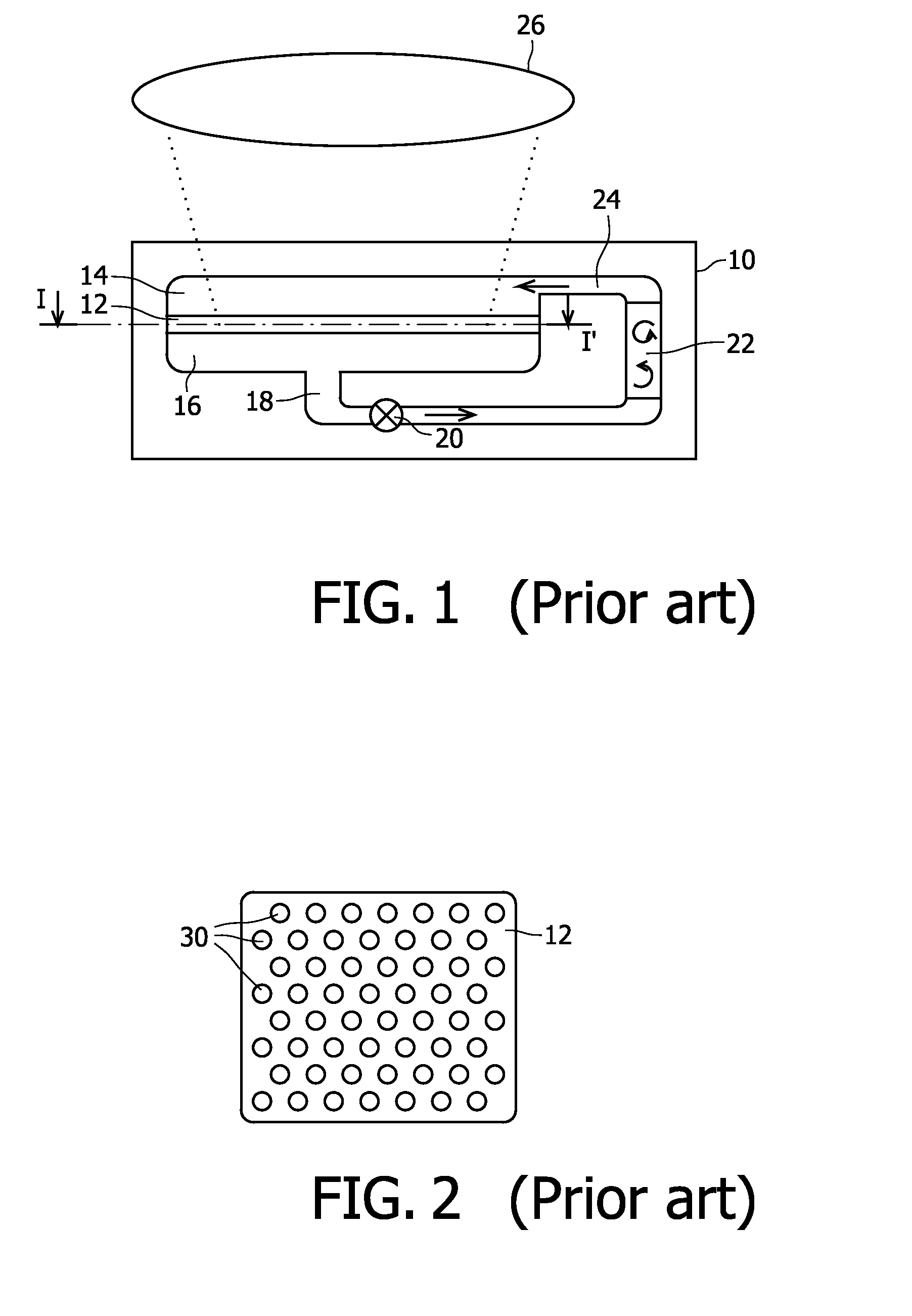
[0039]FIG. 1 shows a diagrammatical cross-sectional view of a prior art device. Herein, the device comprises a housing 10, with a membrane 12, contacted by a first volume 14 and a second volume 16. Via a drain 18, a pump 20 pumps fluid in the direction of the arrow towards mixer 22, and from there, via feed 24 into the first volume 14.

[0040]An optical inspection device is indicated very diagrammatically by reference numeral 26.

[0041]In the prior art device shown here, the sample fluid is pumped through the membrane 12, into or onto which one or more indicator substances have been applied in so-called spots. When the sample fluid passes the membrane, the fluid will contact the indicator substances, and depending on the composition of the fluid, one or more of those indicator substances will either bind to a part of the fluid or undergo some change, in both cases indicating the presence of some substance, micro-organism etc. in the sample fluid.

[0042]In the device shown, only a small ...


PUM

PropertyMeasurementUnit
diameteraaaaaaaaaa
diameteraaaaaaaaaa
widthaaaaaaaaaa

Abstract

The invention relates to a microfluidic device for detection of a substance in a sample fluid, and to a cartridge for performing a biological assay, containing such a device. The microfluidic device comprises two housing parts (52, 54) with a porous membrane (50) there between. Each housing part has recesses, or channel parts, (56-1, 56-2, 56-n, 58-1, 58-2, 58-n) that are connected via a recess of the opposite housing part, and through the membrane (50), such that an unbranched channel is defined for the sample fluid. At one or more of the positions where the channel crosses the membrane (50), a spot (48-1, 48-2, 48-n) with an immobilized indicator substance is present, to which a target substance in the sample fluid may bind. An advantage of the present device is that in principle all of the sample fluid passes each spot. Hence there is no need to recirculate and/or mix the sample fluid, as is the case in devices with parallel flow-through paths for the fluid. The device will therefore be simpler, and give a more reliable detection result.

Description

FIELD OF THE INVENTION[0001]The invention relates to a microfluidic device for performing detection of a substance in a sample fluid, the device comprising a porous membrane with a first surface and a second surface, and with a plurality of spots with at least one immobilized indicator substance, a first housing part with a first volume for holding sample fluid, and contacting the first side of the membrane, a second housing part with a second volume for holding sample fluid, and contacting the second side of the membrane.BACKGROUND OF THE INVENTION[0002]Microfluidic devices are generally used to handle small amounts of fluid. In particular, in fields like molecular diagnostics biosensors et cetera, small amounts of sample fluid, such as blood or other bodily fluids, are tested on the presence of certain substances or micro-organisms, etc., often called target substances. Thereto, the sample fluid is made to contact one or more indicator substances, provided on or in the membrane in...

Claims


Application Information

Patent Timeline
Patent Type & Authority Applications(United States)
IPC IPC(8): G01N1/00
CPCB01D2313/086B01L3/5027B01L3/502753B01L2300/0636B01L2300/0681B01L2300/0861B01L2300/0887
Inventor WIMBERGER-FRIEDL, REINHOLDDE WITZ, CHRISTIANE
Owner KONINKLIJKE PHILIPS ELECTRONICS NV
Why Eureka
Try Eureka