In-Line Mini Sprinklers System and Method and Apparatus for Making Same

a mini sprinkler and sprinkler technology, applied in the field of irrigation, can solve the problems of reducing the advantage of employing the drip emitter method, reducing the cost of deployment, and increasing the difficulty of the deployment task

Active Publication Date: 2008-10-23
RIVULIS PLASTRO LTD
View PDF19 Cites 37 Cited by
  • Summary
  • Abstract
  • Description
  • Claims
  • Application Information

AI Technical Summary

Benefits of technology

[0031]In an additional and different aspect of the present invention, the manner of manufacturing an in-line system of mini sprinklers in accordance with the present invention, embodies a manufacturing method that includes the steps of—continuous manufacturing of a tubular conduit having inner and outer surface areas, adapted to enable flow of liquid under pressure in it, timed feeding and mounting of at least one mini sprinkler unit to the tubular conduit during the process of its continuous manufacturing in a manner that the sprinkler unit would be at least substantially i

Problems solved by technology

The disadvantages of using low volume irrigation through drip emitters, is its “pointed” mode of irrigation.
This solution—increasing the density of branches and of drip emitters per branch, obviously reduces the advantage of employing the drip emitters method, because the quantity of required equipment increases significantly (and also the deployment tasks become more costly and difficult).
As we have pointed above, installation of the integral drip line for operation in the field might be mechanized, and hence efficient and at low cost, but the integral drip line do not offer an answer to the problem we posed above—namely the drawback of missing the localized irrigation, namely the deterrent small area on the ground that is wetted by the drip emitters.
On the other hand, the drawbacks of the low volume irrigation by the mini sprinklers method, lies in the r

Method used


Image

  • In-Line Mini Sprinklers System and Method and Apparatus for Making Same
  • In-Line Mini Sprinklers System and Method and Apparatus for Making Same
  • In-Line Mini Sprinklers System and Method and Apparatus for Making Same

Examples


Embodiment Construction

[0048]For the sake of convenience, the description of the present invention is presented in terms of agricultural irrigation. As already pointed out, the invention is not restricted solely for tasks of agricultural irrigation, neither is it restricted just to irrigation with water as the only liquid that may be used. On the contrary—the invention is applicable to irrigation, wetting and flushing (rinsing) using other liquids, such as detergents or water in a solution with fertilizing materials and so on.

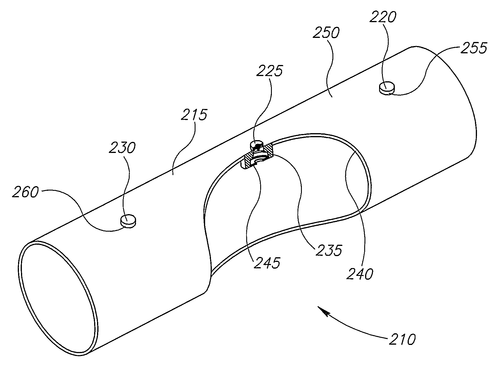
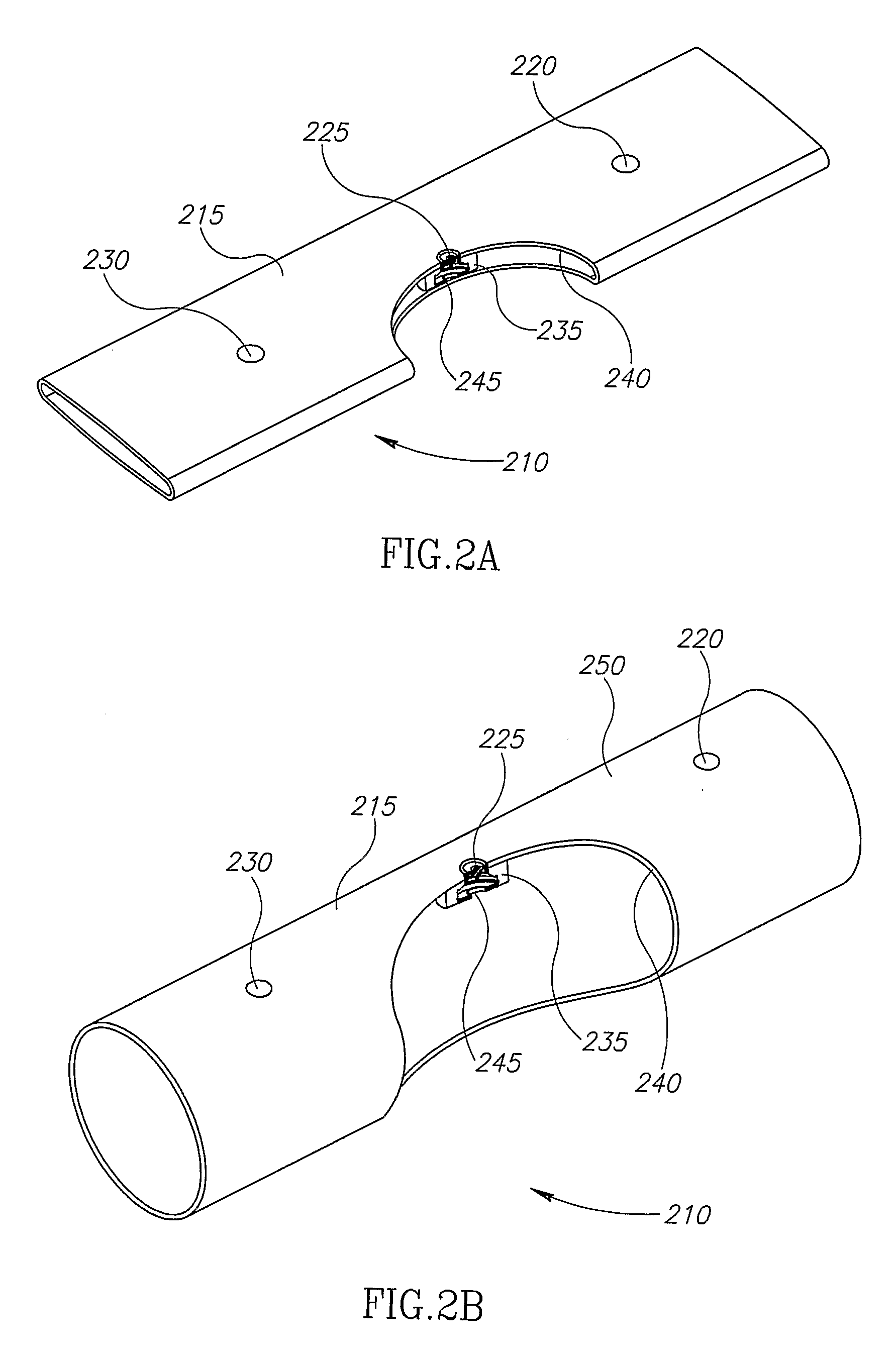
[0049]Referring to figures numbered 2a, 2b and 2c. These figures constitute illustrations (partly in cross sections) of an example of a system 210 for low volume irrigation example in accordance with the present invention.

[0050]In FIG. 2a, a typical sector of an in-line system of mini sprinklers 210 is presented at its closed state, before driving / forcing liquid to flow into the system. System 210 comprises a tubular conduit 215, fitted to conduct a flow of liquid under pressure in i...


PUM

PropertyMeasurementUnit
Widthaaaaaaaaaa
Widthaaaaaaaaaa
Pressureaaaaaaaaaa

Abstract

The present invention relates to An in-line system of mini sprinklers, comprising a tubular conduit having inner and outer surface areas, fitted for a liquid flow under pressure through it and formed with at least one opening along its length; and at least one mini sprinkler unit that is at least substantially embedded within said tubular conduit, coupled to flow of said liquid within it and mounted to it around said opening, and comprises—a mobile liquid distributing assembly movable through said opening, such that when liquid's pressure in said tubular conduit increases, said liquid distributor moves and protrudes beyond said outer surface area of said tubular conduit in order to sprinkle said liquid outwards of said tubular conduit.

Description

FIELD OF THE INVENTION[0001]The invention relates to the domain of irrigation, including agricultural irrigation and flushing (rinsing) areas or wetting surfaces, and fundamentally—in the field of irrigation systems of low volumes, employing mini sprinklers, and the methods for manufacturing these systems.BACKGROUND OF THE INVENTION[0002]Irrigation in low volumes is noted and well known in the domain of modern agricultural irrigation. In general, the subject is an irrigation method designated to deliver the water to a specified and as accurate as practical to a defined area, with correct time and simultaneously providing nutrients (fertilizing) materials to the plants together with the water, at the correct dosage and concentration. The common range of pressures and throughput rates of the water in low volume irrigation is 0.5 to 4 atmospheres and 1 to 200 liters per hour.[0003]There are two major low volume irrigation methods—drip irrigation and irrigation by sprinkling.[0004]The d...

Claims


Application Information

Patent Timeline
IPC IPC(8): B05B15/00D01D5/24B28B11/00B05B15/74
CPCA01G25/02B05B1/202B05B1/262B05B1/3006B05B15/10B05B15/74
Inventor EINAV, ZVIKAGOLAN, ZVI
Owner RIVULIS PLASTRO LTD
Why Eureka
Try Eureka