
Shape preserving mappings to a surface

Active Publication Date: 2008-10-23
AUTODESK INC
View PDF14 Cites 16 Cited by
  • Summary
  • Abstract
  • Description
  • Claims
  • Application Information

AI Technical Summary

Benefits of technology

[0012]Given a three dimensional detail model that is defined over a reference plane, one or more embodiments of the invention solve the problem of creating a copy of the detail model that conforms

Problems solved by technology

However, this parameterization does not necessarily lead to a shape preserving mapping, and will generally introduce undesirable distortions.
Prior art solutions fail to provide shape preserving mapping with geometries wherein a detail model is mapped to an original smooth destination surface.

Method used


Image

  • Shape preserving mappings to a surface
  • Shape preserving mappings to a surface
  • Shape preserving mappings to a surface

Examples


Embodiment Construction

[0027]In the following description, reference is made to the accompanying drawings which form a part hereof, and which is shown, by way of illustration, several embodiments of the present invention. It is understood that other embodiments may be utilized and structural changes may be made without departing from the scope of the present invention.

Overview

[0028]Given a destination surface and a tessellation of said destination surface, and a parameterization of said tessellation: one or more embodiments of the invention calculate a map from the (u,v) plane that, as its final step, calculates a projection (or closest point determination) from said tessellation to the original destination surface. Additional maps are created from a detailed model surface to the destination space / surface based on the mapping.

Hardware and Software Environment

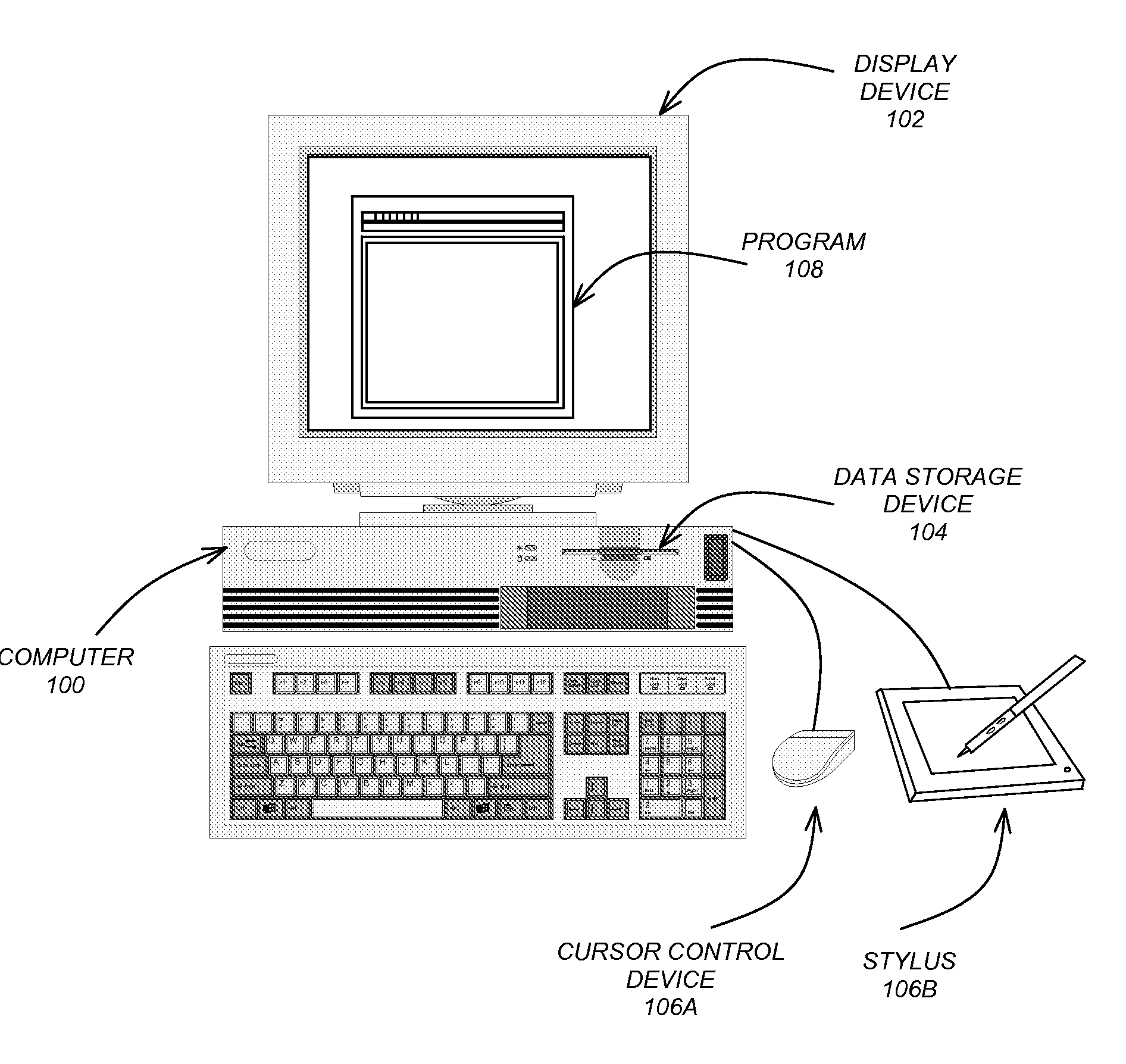
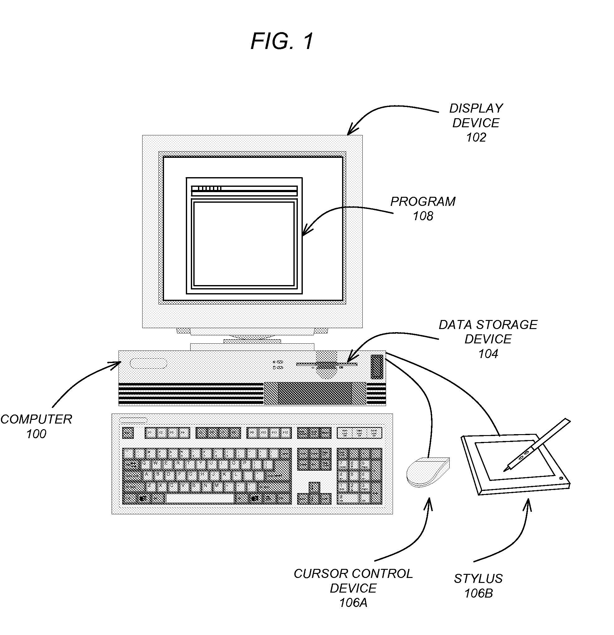
[0029]FIG. 1 is an exemplary hardware and software environment used to implement one or more embodiments of the invention. Embodiments of the inventi...


PUM


Abstract

A method, apparatus, and article of manufacture provide the ability to map a detail model to a destination while preserving the shape of the detail model. A destination surface (that is a smooth surface) is obtained. The destination surface is tessellated to generate a mesh representation of the destination surface. A parameterization of the mesh representation is then generated. Reverse mapping is conducted from a point of a detail model surface to a point of the destination surface via the parameterization and mesh representation.

Description

CROSS-REFERENCE TO RELATED APPLICATIONS[0001]This application is related to the following commonly-assigned patents, which patents are incorporated by reference herein:[0002]U.S. Pat. No. 7,133,044, entitled “SYSTEM OF FEATURE-BASED SURFACE MAPPING”, by Jerome Maillot and Xiaohuan Wang, issued on Nov. 7, 2006; and[0003]U.S. Pat. No. 7,034,824, entitled “SYSTEM AND METHOD FOR COMPUTING A CONTINUOUS LOCAL NEIGHBORHOOD AND PARAMETERIZATION”, by Jerome Maillot, issued on Apr. 25, 2006.BACKGROUND OF THE INVENTION[0004]1. Field of the Invention[0005]The present invention relates generally to three-dimensional (3D) modeling, animation, effects, and rendering applications, and in particular, to a method, apparatus, and article of manufacture for preserving the shape of an object when mapping an object to a surface in a 3D model.[0006]2. Description of the Related Art[0007]In 3D modeling, animation, effects, and rendering applications, it is desirable to place and display one object (referre...

Claims


Application Information

Patent Timeline
IPC IPC(8): G06T15/30
CPCG06F17/50G06T19/20G06T2219/2021G06F30/00
Inventor LIEPA, PETER E.MA, VINCENT C. H.
Owner AUTODESK INC
Learn More