Hole Saw Assembly

a technology of assembly and hole saw, which is applied in the direction of turning apparatus, rod connection, ropes and cables for vehicles/pulleys, etc., can solve the problems of easy loss, difficulty in assembling the apparatus, and loose mandrel of the hole saw

Active Publication Date: 2008-10-23
KEIGHTLEY KYM JOHN
View PDF12 Cites 35 Cited by
  • Summary
  • Abstract
  • Description
  • Claims
  • Application Information

AI Technical Summary

Problems solved by technology

However in very large hole saws, the rotational force developed (or torque required to rotate the hole saw) when operating the mandrel in heavier machinery may strip the thread where the hole saw couples with the boss.
The problem with this type of arrangement is that it is awkward to asse...

Method used


Image

  • Hole Saw Assembly
  • Hole Saw Assembly
  • Hole Saw Assembly

Examples


Embodiment Construction

[0035]The following detailed description of the invention refers to the accompanying drawings. Although the description includes exemplary embodiments, other embodiments are possible, and changes may be made to the embodiments described without departing from the spirit and scope of the invention. Wherever possible, the same reference numbers will be used throughout the drawings and the following description to refer to the same and like parts.

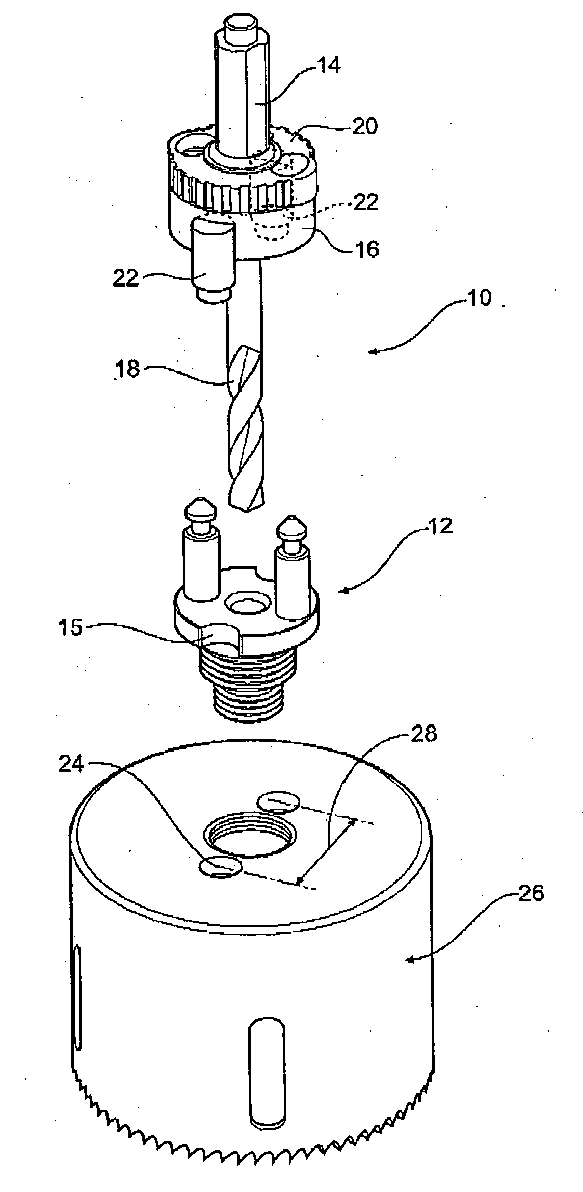
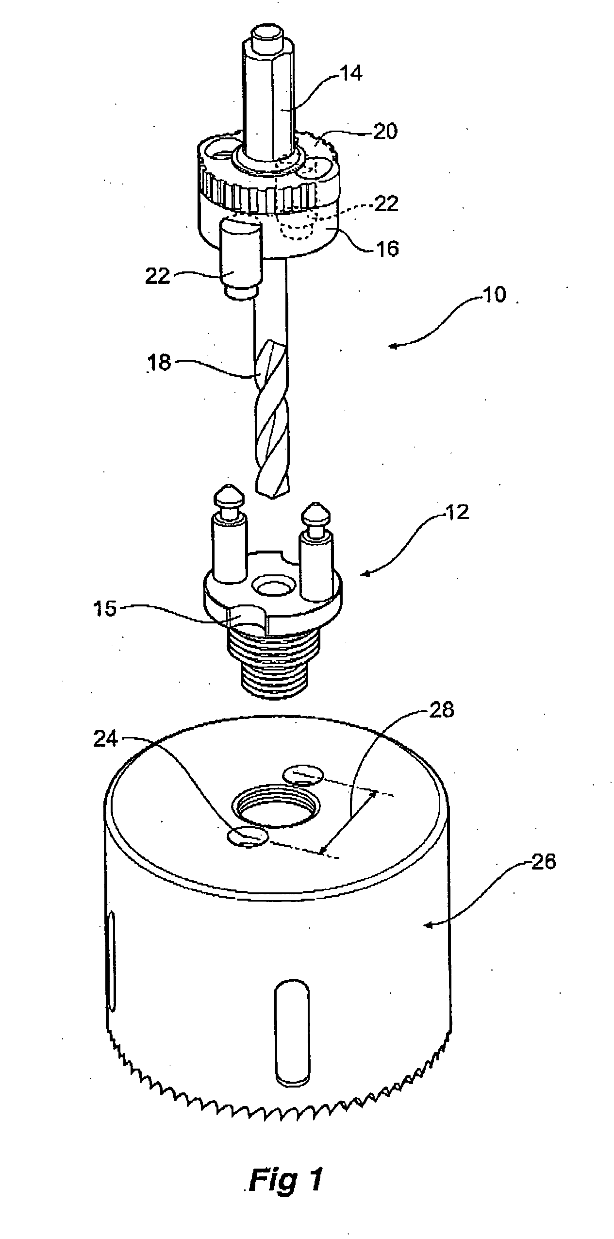
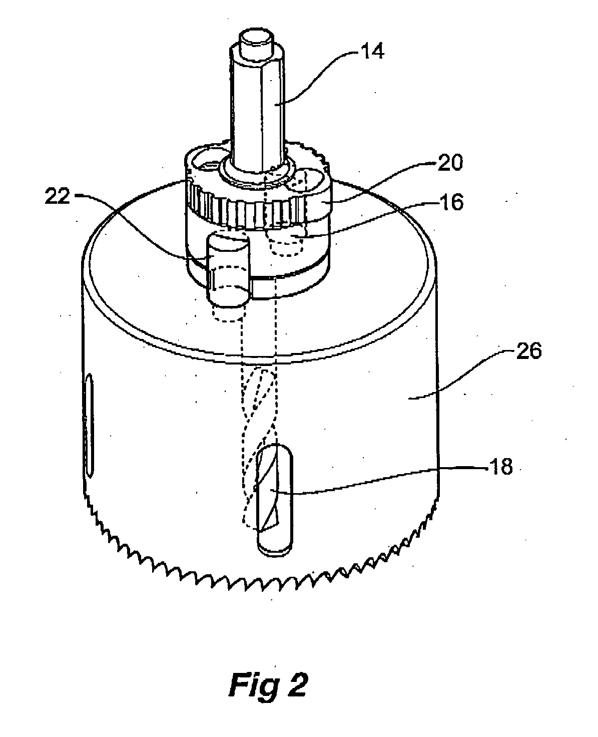
[0036]The present invention, as mentioned above, relates to an improvement in a hole-saw assembly of the type described in PCT / AU03 / 01296 and that includes a hole-saw having at one end a plurality of cutting teeth and at the other end two shaft. The assembly includes a mandrel coaxially aligned with said hole-saw and including a body having two bores there through, coaxially aligned with said shafts. An annulus located on top of the body is coaxially aligned with said mandrel and hole saw and includes two holes, the annulus rotatable aroun...


PUM

PropertyMeasurementUnit
Compressibilityaaaaaaaaaa

Abstract

The present invention relates to a hole-saw assembly (10) including a hole saw (26) having at one end a plurality of cutting teeth and at the other end two shafts. The assembly includes a mandrel (16) coaxially aligned with said hole-saw and including a body having two bores there through coaxially aligned with said shafts. An annulus (20) located on top of the body is coaxially aligned with said mandrel and hole saw and includes two holes, the annulus rotatable around its longitudinal axis from a first to a second position. In the first position the annulus holes are aligned with the bores and shafts allowing the shafts to be freely insertable and removable and in the second position the holes are misaligned to lock the shafts to the annulus. The mandrel further includes a pair of driving pins (22) adapted to engage driving apertures (24) found in hole saws especially larger ones. Typically the driving pins may biased to enable the assembly to be used even with those hole saws that do not include driving apertures and that also enables easier assembly of the device. A compressible O-ring (42) may further facilitate the operation of the assembly. This device avoids the problem of thread stripping.

Description

BACKGROUND OF THE INVENTION[0001]The present invention relates to a holes saw and in particular to a rotatable hole saw supported by a mandrel which is inserted in a drill chuck or the like.[0002]Hole saws are widely used to cut circular holes for many applications. Typically a hole saw is cylindrically shaped with cutting teeth at one end and a threaded boss at the other for screwing into a mandrel for rotational operation in a drill.[0003]A pilot drill extends from the centre of the mandrel and through the centre of the hole saw as it is screwed onto the mandrel. As it always protrudes further than the length of the hole saw blade and hence contacts the material to be cut first the pilot drill is the first to cut the hole in the material and acts as the exact centre of the hole saw diameter. This hole then acts as a guide or “pilot” around which the hole saw then concentrically cuts a larger hole.[0004]In a previous application PCT / AU02 / 011296, whose contents are incorporated by e...

Claims


Application Information

Patent Timeline
IPC IPC(8): B27B5/12B23B51/04B27B33/18
CPCB23B51/0426B23B51/0473B23B2251/606B23B2260/082B23B2260/138Y10T408/95Y10T403/7007Y10T403/56Y10T279/16Y10T403/59Y10T408/895
Inventor KEIGHTLEY, KYM JOHN
Owner KEIGHTLEY KYM JOHN
Why Eureka
Try Eureka