Abrasive belt for sanding device

a technology of abrasive belts and sanding devices, which is applied in the field of abrasive belts, can solve the problems that work pieces cannot be effectively sanded, ground or abraded by the sand belt, so as to facilitate the sanding or grinding or abrading operation and increase the working life of the sanding bel

Inactive Publication Date: 2008-10-23
CHAO CHING CHI
View PDF4 Cites 1 Cited by
  • Summary
  • Abstract
  • Description
  • Claims
  • Application Information

AI Technical Summary

Benefits of technology

[0011]The primary objective of the present invention is to provide an abrasive belt including a number of spaces or compartments formed therein for receiving the dust or cut chips and for facilitating the sanding or grinding or abrading operation and for increasing the working life for the abrasive belt.

Problems solved by technology

However, after the sanding or grinding or abrading operations, the dust or cut chips may be quickly filled among or between the sanding or grinding or abrading sands or particles such that the work pieces may not be effectively sanded or ground or abraded by the sand belt.
However, similarly, the sand belt also includes a number of sanding or grinding or abrading sands or particles attached or secured onto a planar base belt member for engaging with and for sanding or grinding or abrading work pieces, and the dust or cut chips may also be quickly filled among or between the sanding or grinding or abrading sands or particles after the sanding or grinding or abrading operations, such that the work pieces may not be effectively sanded or ground or abraded by the sand belt.

Method used


Image

  • Abrasive belt for sanding device
  • Abrasive belt for sanding device
  • Abrasive belt for sanding device

Examples


Embodiment Construction

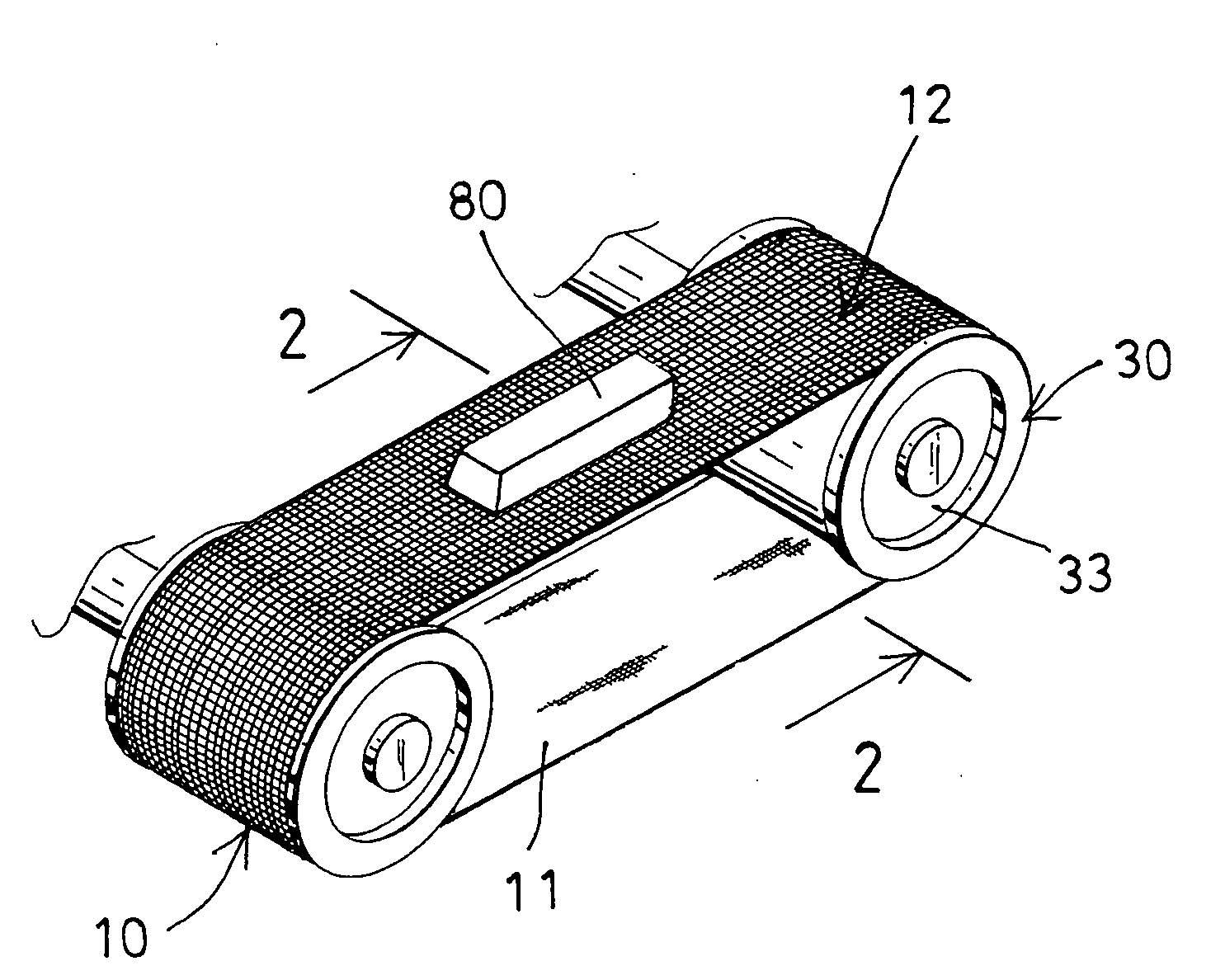
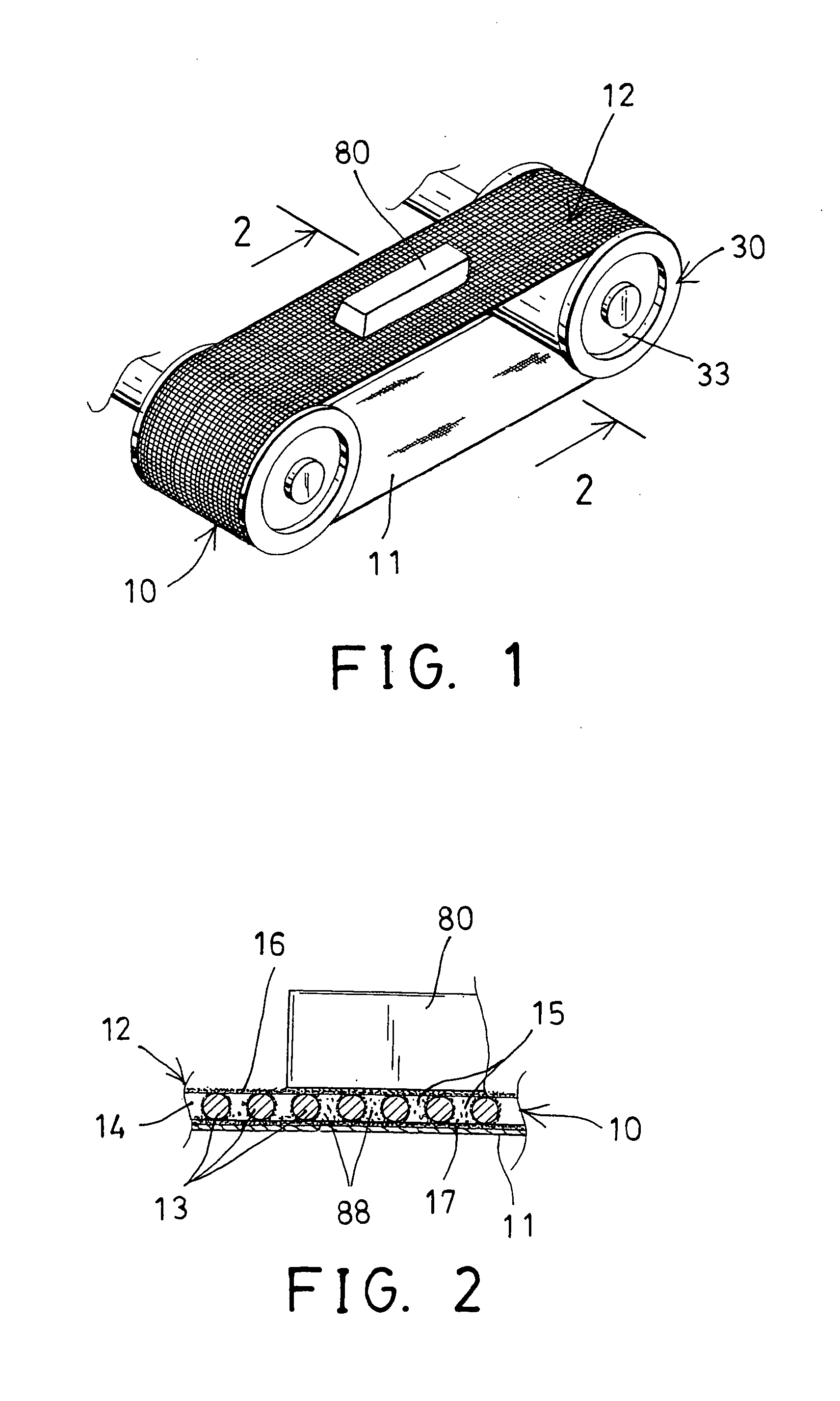
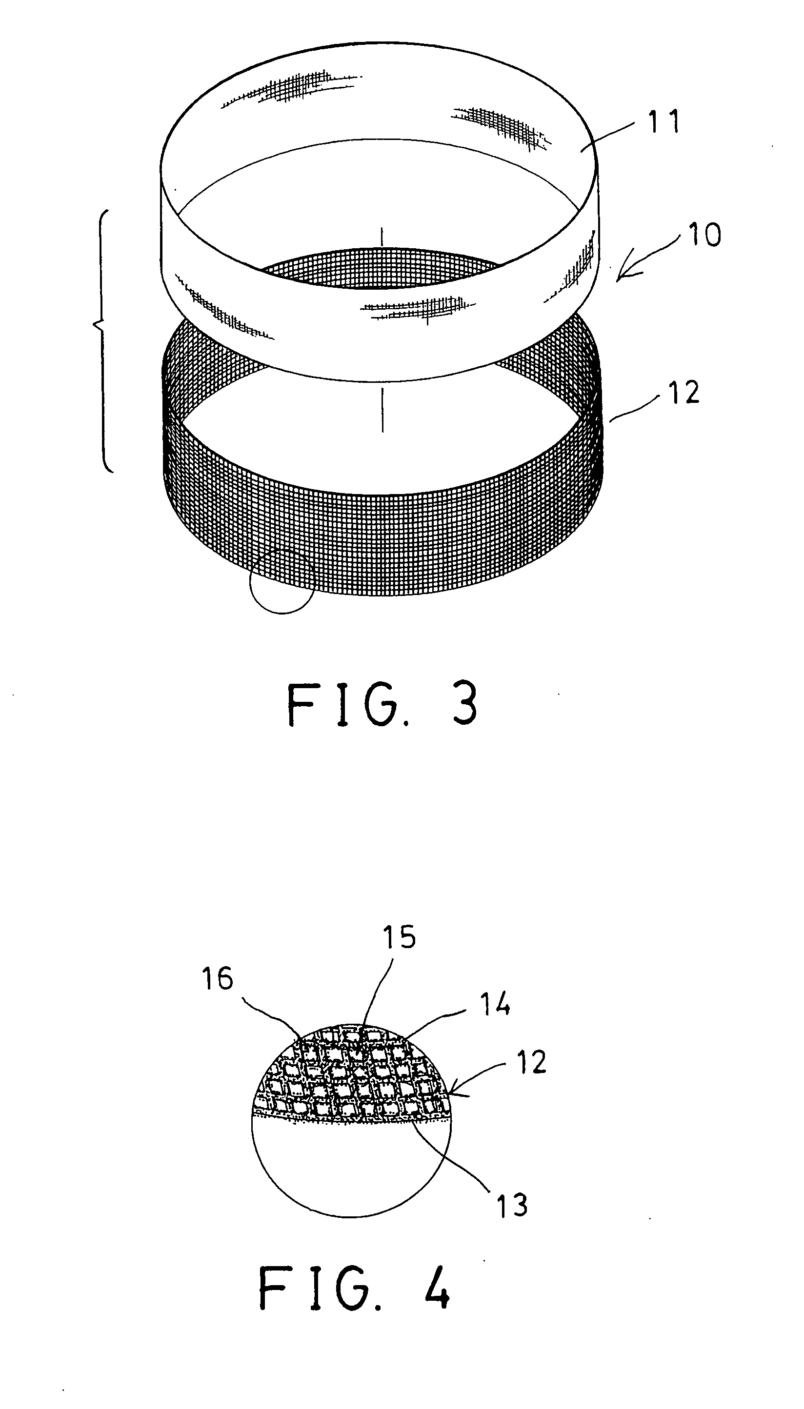
[0021]Referring to the drawings, and initially to FIGS. 1-3, an abrasive belt 10 in accordance with the present invention comprises a planar base layer or member 11, and a net layer or member 12 attached to or engaged onto the base member 11 for forming an endless belt member and for engaging around the pulleys or rollers 33 of a sanding or grinding or abrading machine 30 and for sanding or grinding or abrading work pieces 80.

[0022]As shown in FIGS. 2 and 4, the net member 12 includes a number of longitudinal fibers or fibers or cords 13 and a number of lateral fibers or fibers or cords 14 woven together or secured or welded together as a non-woven structure for forming a number of spaces or compartments or eyelets 15 among or between the cords 13, 14 and for receiving the dust or cut chips 88 (FIG. 2) that will be generated or ground or abraded from the work pieces 80 by the abrasive belt 10.

[0023]The abrasive belt 10 further include a number of sanding or grinding or abrading sand...


PUM


Abstract

An abrasive belt includes a net member having a number of cords secured together for forming a number of eyelets between the cords, and a number of abrading particles applied onto the net member for engaging with a work piece and for abrading the work piece and for abrading cut chips from the work piece and for allowing the cut chips to be received and engaged in the eyelets of the net member. The abrading particles may be applied onto an outer portion or an inner portion of the net member. A base member may be attached or engaged in the net member for supporting the net member which may include a number of longitudinal cords and lateral cords secured together.

Description

BACKGROUND OF THE INVENTION[0001]1. Field of the Invention[0002]The present invention relates to an abrasive belt, and more particularly to an abrasive belt including a number of spaces or compartments formed therein for receiving the dust or cut chips and for facilitating the sanding or grinding or abrading operation and for increasing the working life for the abrasive belt.[0003]2. Description of the Prior Art[0004]Typical abrasive belts or members comprise an endless sand belt for engaging around the rollers or pulleys of a sanding or grinding or abrading machine and for sanding or grinding or abrading work pieces.[0005]For example, U.S. Pat. No. 5,168,656 to Jolly et al., and U.S. Pat. No. 5,361,546 to Jonsson disclose two of the typical sanding or grinding or polishing machines each also comprising an endless sand belt for engaging around the rollers or pulleys.[0006]Normally, the sand belt includes a planar base belt member having a number of sanding or grinding or abrading sa...

Claims


Application Information

Patent Timeline
Patent Type & Authority Applications(United States)
IPC IPC(8): B24D11/00
CPCB24D11/02
Inventor CHAO, CHING-CHI
Owner CHAO CHING CHI
Why Eureka
Try Eureka