Prosthesis Fixation Apparatus and Methods

a technology of prosthesis and fixation apparatus, which is applied in the field of prosthesis fixation, can solve the problems of affecting the stability of the stent, and the weakened outward spring force of the self-expanded stent-graft, and the inability to prevent migration

a technology of prosthesis and fixation apparatus, which is applied in the field of prosthesis fixation, can solve the problems of affecting the stability of the stent, and the weakened outward spring force of the self-expanded stent-graft, and the inability to prevent migration

US20080262597A1Inactive Publication Date: 2008-10-23MEDTRONIC VASCULAR INC

Image

  • Prosthesis Fixation Apparatus and Methods
  • Prosthesis Fixation Apparatus and Methods
  • Prosthesis Fixation Apparatus and Methods

Examples


Embodiment Construction

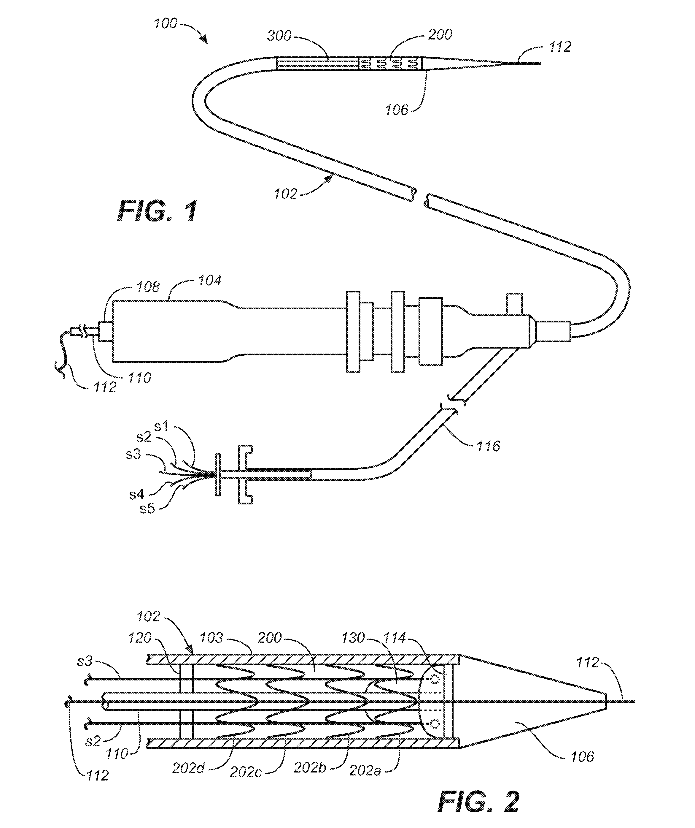
[0043]The following description will be made with reference to the drawings where when referring to the various figures, it should be understood that like numerals or characters indicate like elements. When referring to catheters, delivery devices and loaded fasteners described below the proximal end is the end nearest the operator and the distal end is farthest from the operator.

[0044]Referring to FIG. 1, one embodiment of a prosthesis delivery system according to the invention is shown and generally designated with reference numeral 100. Prosthesis delivery system 100 comprises catheter 102, which includes catheter sheath 103, control handle 104, flexible tapered tip member (or obturator 106), which can form a portion of the distal end of the catheter. In the embodiment illustrated in FIG. 1, system 100 is equipped with prosthesis 200 and fastener delivery apparatus 300.

[0045]Handle 104 includes an inlet 108, through which central guidewire lumen 110 enters the handle and extends ...


PUM


Abstract

Apparatus and methods for endoluminally advancing a tubular prosthesis and a plurality of fasteners to a site in a lumen in a human body and passing the fasteners from an inner surface of the prosthesis through the prosthesis and a wall of the lumen to secure the prosthesis to the wall. Embodiments include simultaneous deployment of fasteners using a graft alone or in conjunction with a stent graft. Another arrangement includes guide lines to guide the end of the fixation deployment device to a specific location of the wall of the prosthesis.

Description

FIELD OF THE INVENTION[0001]The invention relates to prosthesis fixation in a passageway in a human body such as an artery.BACKGROUND OF THE INVENTION[0002]Tubular prostheses such as stents, grafts, and stent-grafts (e.g., stents having an inner and / or outer covering comprising graft material and which may be referred to as covered stents) have been used to treat abnormalities in passageways in the human body. In vascular applications, these devices often are used to replace or bypass occluded, diseased or damaged blood vessels such as stenotic or aneurysmal vessels. For example, it is well known to use stent-grafts, which comprise biocompatible graft material (e.g., Dacron® or expanded polytetrafluoroethylene (ePTFE)) supported by a framework (e.g., one or more stent or stent-like structures), to treat or isolate aneurysms. The framework provides mechanical support and the graft material or liner provides a blood barrier.[0003]Aneurysms generally involve abnormal widening of a duct...

Claims


Application Information

Patent Timeline
23 Oct 2008
Publication
US20080262597A1
IPC
A61F2/06
CPC
A61B17/064; A61B17/068; A61B17/115; A61B2017/1157; A61F2/064; A61F2/07; A61F2/848; A61F2/954
Inventors
XIAO, JIA HUA; MARILLA, BRENNAN